NetAnim – An Animator for ns-3 Simulations
NetAnim is an offline network animator tool that now ships along with the ns-allinone-3.xx package.
It can animate the ns-3 network simulation using an XML trace file that is generated as an output during simulation.
So, the necessary steps for creating this XML trace file and setting its related attributes should be done in the ns-3 simulation code itself.
For a beginner who starts learning ns2, the animation that is created by NetAnim will be a more attractive factor in learning and understanding a simulation. Undoubtfully, each and every beginner of ns-3 will be very happy while seeing the first animator output of their simulation on NetAnim for the very first time. So let us enjoy seeing our first network animation on NetAnim.
In this example, we are going to extend the simulation script that we prepared in a previous article http://www.projectguideline.com/start-experiencing-ns-3-with-a-simple-simulation/
SimpleNS3Simulation2.cc
#include “ns3/core-module.h”
#include “ns3/network-module.h”
#include “ns3/point-to-point-module.h”
#include “ns3/internet-module.h”
#include “ns3/applications-module.h”
#include “ns3/mobility-module.h”
#include “ns3/netanim-module.h”
using namespace ns3;
int
main (int argc, char *argv[])
{
NodeContainer nodes;
nodes.Create (2);
PointToPointHelper channel;
channel.SetDeviceAttribute (“DataRate”, StringValue (“5Mbps”));
channel.SetChannelAttribute (“Delay”, StringValue (“2ms”));
NetDeviceContainer netDevices;
netDevices = channel.Install (nodes);
InternetStackHelper ipStack;
ipStack.Install (nodes);
Ipv4AddressHelper ipAddresses;
ipAddresses.SetBase (“192.168.1.0”, “255.255.255.0”);
Ipv4InterfaceContainer ipinterfaces = ipAddresses.Assign (netDevices);
UdpEchoServerHelper udpEchoServer (9);
ApplicationContainer serverApps = udpEchoServer.Install (nodes.Get (1));
serverApps.Start (Seconds (1.0));
UdpEchoClientHelper udpEchoClient (ipinterfaces.GetAddress (1), 9);
ApplicationContainer clientApps = udpEchoClient.Install (nodes.Get (0));
clientApps.Start (Seconds (2.0));
MobilityHelper mobility;
mobility.SetPositionAllocator (“ns3::GridPositionAllocator”,
“MinX”, DoubleValue (0.0), “MinY”, DoubleValue (0.0),”DeltaX”, DoubleValue (5.0), “DeltaY”, DoubleValue (10.0),
“GridWidth”, UintegerValue (5), “LayoutType”, StringValue (“RowFirst”));
mobility.SetMobilityModel (“ns3::ConstantPositionMobilityModel”);
mobility.Install (nodes);
AnimationInterface anim (“SimpleNS3Simulation_NetAnimationOutput.xml”);
anim.SetConstantPosition (nodes.Get(0), 0, 5);
anim.SetConstantPosition (nodes.Get(1), 10, 5);
Simulator::Run ();
}
We just added two lines at the top and few lines at the bottom to create XML file output for visualizing on the NetAnim tool. Even though there will not be any mobility in this wired network scenario, a mobility model should be attached to the nodes to display the nodes at the appropriate locations.
Running the Script “SimpleNS3Simulation2.cc”
If you run the script, it will not generate any interesting outputs in the terminal; because I just removed all the lines which actually shows some “LogComponent” outputs to make you understand how we can use the Log Components in a typical simulation. There is no need to enable the Log Components in the simulation script itself – later we may enable it by setting the environment variable before running the simulation.
Download the file “SimpleNS3Simulation2” and copy it to the folder ns-allinone-3.25/ns-3.25/scratch
Change to the directory “ns-3.25”
$ cd ns-allinone-3.25/ns-3.25/
And run the simulation
$ waf –run SimpleNS3Simulation2
After running the simulation, an XML trace file will be generated in the name “SimpleNS3Simulation_NetAnimationOutput.xml”
Now we have to run the NetAnim as follows (here we assume that the path to NetAnim binary is already set in the environment variable):
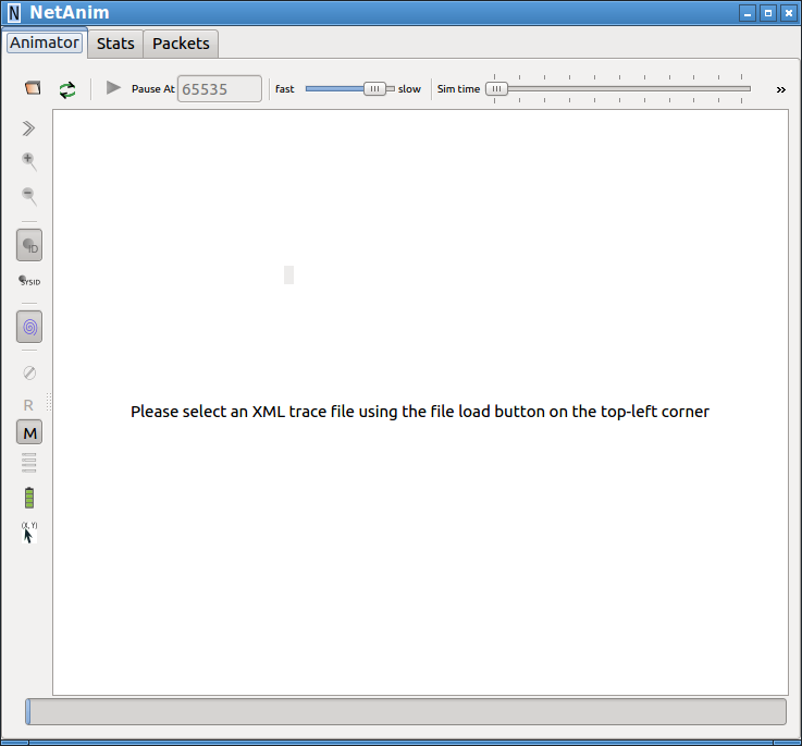
$NetAnim
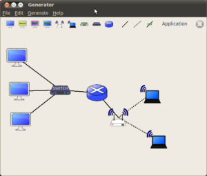
This command will open a blank NetAnim User Interface with a blank window.
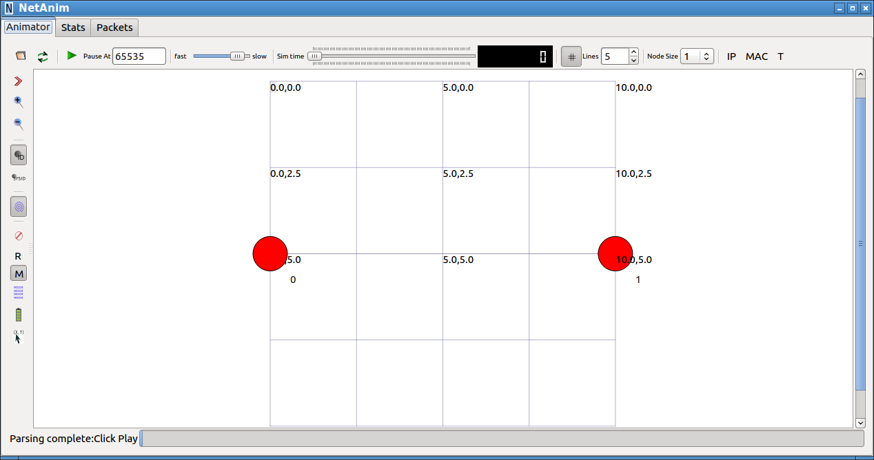
Now we have to open the “SimpleNS3Simulation_NetAnimationOutput.xml” file using the left-top folder icon on the toolbar.
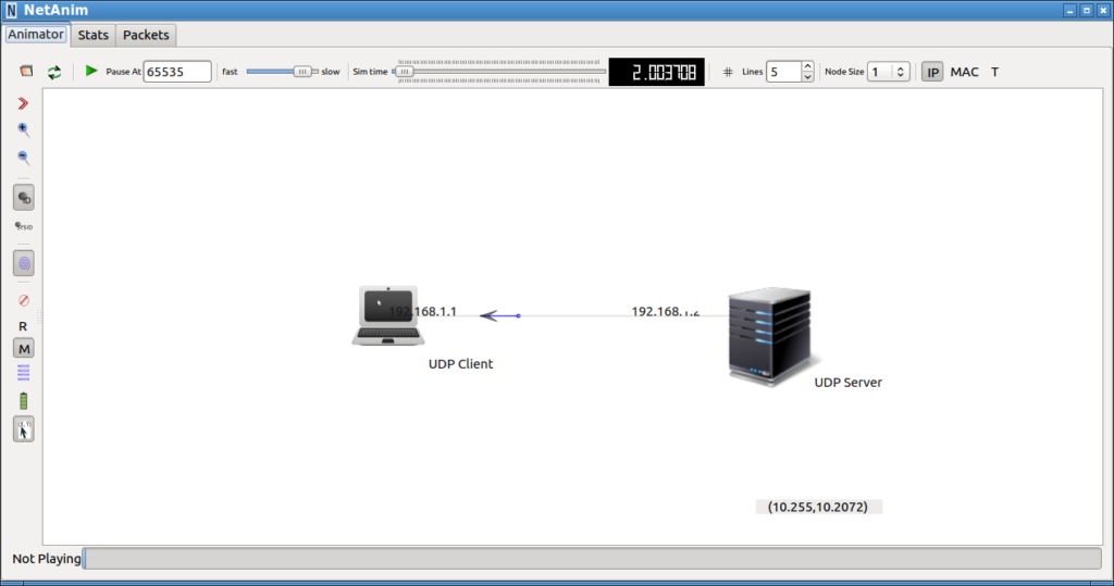
This will show the nodes at positions that we set in the simulation script.
Customizing the Visual Output in NetAnim
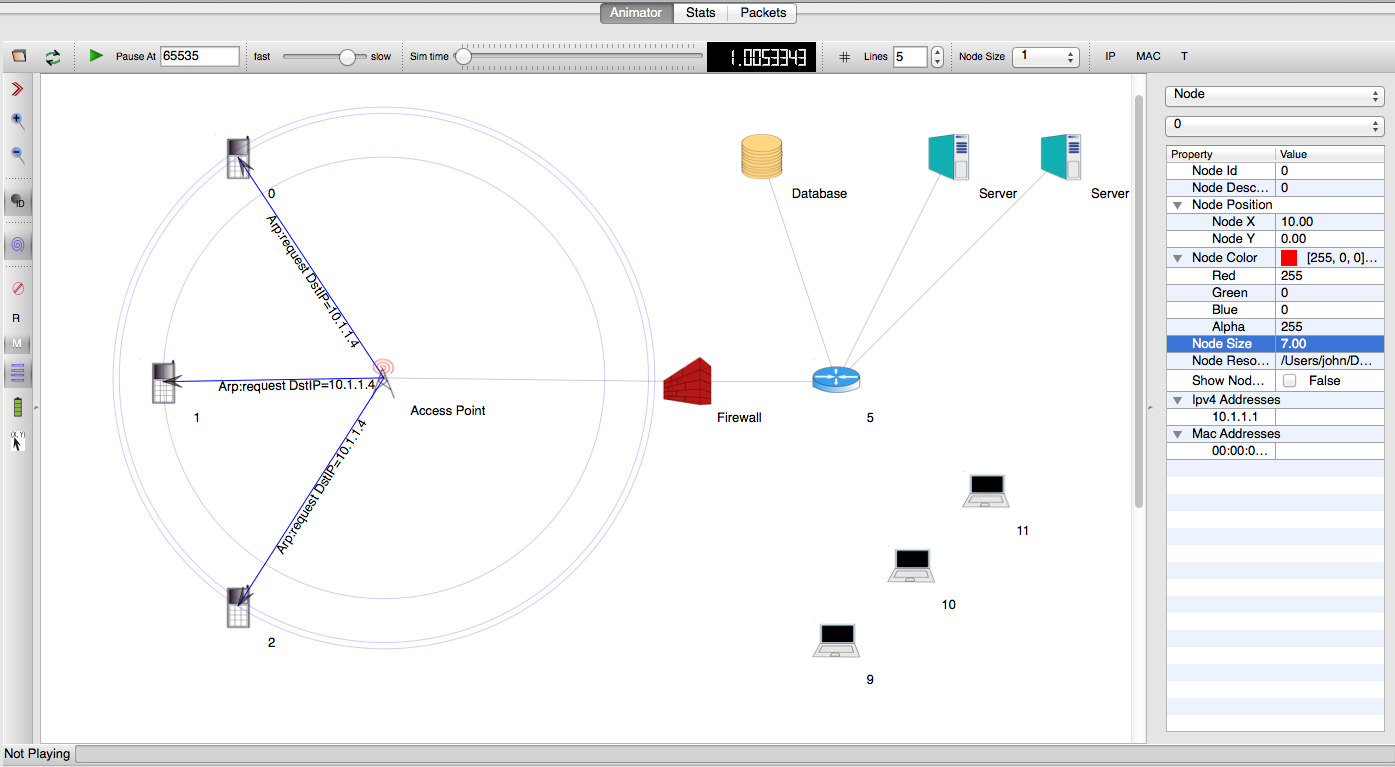
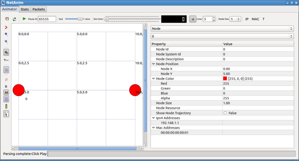
By using the options available in the NetAnim user interface, we can customize the properties of the Nodes and display some additional information.
For example, double-clicking on a node will open a property editor from which we can set some basic display properties of a node.
The following output shows the same network scenario after updating node display attributes.
The graphical and textual output and properties of the entities on the network animator canvas can be directly set from the ns-3 simulation script itself. We will learn about it in another article.
Related Articles
Simulating Freeway Mobility Model under ns-3 Using Trace Files Generated by Mobisim
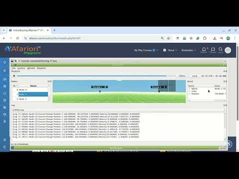
ns-3 VANET Simulation – 3D Visualization of 2D Gridway Mobility using NetSimulyzer
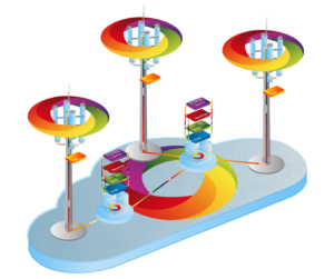
Visualizing ns-3 Simulations in 3D
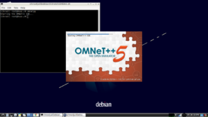
For visualizing a network in 3D, one can use NetSimulyzer. The following articles show the installation procedure :
Installing NetSimulyzer 3D Visualization Tool under Debian/Ubuntu
Installing NetSimulyzer 3D Visualization Support Add-on Module in ns-3 under Debian/Ubuntu
You may do visualizations like the following using the NetSimulyzer Tool.
Read the following post for more information
Implementation of Spring Mobility Model for ns-3 and Visualizing it in 3D along with Circle Mobility
You may learn more about NetSimulyzer from the following links :
 Take Me to Afarion ns-3 iPlayground