Note:
This project is almost a two-decade old. If you are an electronics hobbyist, then you may try this. If you are a graduate or postgraduate student, then please try to do a project on some latest technologies.
No more support will be provided for any of these old student-contributed projects. Even you will not get any reply if you raise any query in this regard – sorry.
Introduction
Sensor networks present unprecedented opportunities for a broad spectrum of applications such as industrial automation, situation awareness, tactical surveillance for military applications, environmental monitoring, chemical/biological detection etc. Recent technological advances have enabled distributed information gathering from a given location/region by deploying a large number of networked tiny microsensors which are low power devices equipped with programmable computing, multiple sensing and communication capability. Microsensor systems enable the reliable monitoring and control of a variety of applications.
This project addresses the problems of wired and wireless sensor networks and will provide a cost-effective solution for a simple sensor network using 8051 microcontroller.
The Proposed Architecture
The two main architecture alternatives used for data communication in a sensor network are the hierarchical and the flat network architectures. The hierarchical network architecture is energy efficient for collecting and aggregating data within a large target region, where each node in the region is a source node. Hence hierarchical network protocols are used when data is to be collected from the entire sensor network. A flat network architecture is more suitable for transferring data between a source-destination pair separated by a large number of hops.
The following diagram explains the proposed sensor network architecture.
The Proposes Sensor Network Architecture
The sensor network is formed by connecting the Tx lines of 8051 to the Rx Lines of the neighboring 8051s. Thus the sensor data available on each and every 8051 nodes can be transferred to the PC which is connected at the right-bottom of the network. For this, a suitable protocol should be implemented in each and every node of the sensor network.
Since 8051s contain only one Full duplex UART, for single node we will require two 8051 while designing a wired sensor network. If we design it in a wireless manner we may use only one microcontroller per node. But, for this project, a slightly modifies version of a proposed sensor network was implemented by using only one microcontroller per node by connecting Tx line of a node with Rx line of another node in a serial fashion.
Sensor networks can be classified into two types based on their mode of operation or functionality and the type of target applications: In Proactive Networks scheme the nodes periodically switch on their sensors and transmitters, sense the environment and transmit the data of interest. Thus, they provide a snapshot of the relevant parameters at regular intervals and are well suited for applications that require periodic data monitoring. In Reactive Networks scheme, the nodes react immediately to sudden and drastic changes in the value of a sensed attribute and are well suited for time critical applications. Once we have a network, we have to come up with protocols which efficiently route data from the nodes to the users, preferably using a suitable protocol to avoid collisions. In this project, a wired sensor network will be implemented due to its simplicity of design and cost. But the same concept can be wirelessly implemented using simple infrared or short range wireless technologies using the same Rx and Tx lines.
1.2 The Reasons for Selecting 8051 Micro Controller
The 8051 family of microcontroller is selected for implementing the proposed sensor network because it is the most cheapest and commonly available microcontroller in the market. It is based on an architecture which is highly optimized for embedded control systems. It is used in a wide variety of applications from military equipment to automobiles to the keyboard of the PC. The 8051 family of microcontrollers is available in a wide array of variations from manufacturers such as Intel, Philips, and Siemens. These manufacturers have added numerous features and peripherals to the 8051 such as I2C interfaces, analog to digital converters, watchdog timers, and pulse width modulated outputs. Variations of the 8051 with clock speeds up to 40MHz and voltage requirements down to 1.5 volts are available. This wide range of parts based on one core makes the 8051 family an excellent choice as the base architecture for a company’s entire line of products since it can perform many functions and developers will only have to learn this one platform. It has a Full duplex UART, so this micro-controller can be used for constructing the proposed sensor network.
1.3 About the Implementation
The hardware will be assembled on readily available general purpose PCBs and the power for each and every node will be provided from a common power source. Micro switches will be used at all the sensor nodes to provide dummy sensor data. The Firmware of the 8051 nodes will be developed by using suitable programming language. The software at the PC side will be developed using a suitable programming language such as c++ or VC++ for gathering the sensor data and visualizing the whole sensor network.
The System Design And Development
The Circuit Diagram of the Node at PC End
The Circuit Diagram of the Node at PC End
Circuit Description
The top portion of the circuit diagram is contains a 5V regulated power supply using 7805 Voltage Regulator IC.
In the power supply section, 500mA, 230 to 6V step down transformer is used. The 5V power is supplied to the main sensor node and other sensor nodes.
In the middle of the circuit diagram, the 8051 micro controller is Situated. It uses a 11 M.Hz crystal oscillator circuit for it clock. The sensor inputs were simulated by using simple dual pole switches.
In the bottom of the circuit diagram, the MAX 232 level converter is Placed. It is used to interface the serial port of the Micro controller with a PC’s com port.
The Circuit Diagram of the other Nodes
The Circuit Diagram of a Sensor Nodes
Circuit Description
The top right portion of the circuit diagram there is a connector which will provides power and signal to the next stage sensor node.
The bottom left portion of the circuit diagram there is a connector which will provides power and signal from the previous stage of the sensor node.
In the middle of the circuit diagram, the 8051 micro controller is Situated. It uses a 11 M.Hz crystal oscillator circuit for it clock. The sensor inputs were simulated by using simple dual pole switches.
In the bottom of the circuit there is no MAX 232 level converter because, in this stage the TTL logic level of the serial port of the micro controller is directly used.
The Implemented Sensor Network Architecture.
Sensor Network Architecture
Algorithm for Data Transfer in a Sensor Node
1. During the Star-up, Clear all variables and ports.
2. Set serial port communication speed.
3. Setup new random input wait timeout duration to maintain randomness in transmission.
4. Wait for serial input in Rx line until timeout or a input to come and if a input comes then store it in a temporary register.
5. If (timeout or data arrived) then
6. Check it as valid or not using the header field.
7. If it is invalid or incomplete data, then leave it and continue from step 3.
8. If (timeout) then Get Local sensor data in the temporary register and add the node ID to denote its origin.
9. Else Leave the previous node sent data in the temporary register.
10. End if
11. If the data in temporary register is a control message, then set up the node according to the control message then Forward the data in temporary register to the next node by transmitting it in the Tx Line
12. Else If the data in temporary register is a previous node data then Forward the data in temporary register to the next node by transmitting it in the Tx Line
13. Repeat from step 3 again.
About the Firmware Development Platform
Several C compilers are available for the 8051, most of which feature extensions that allow the programmer to specify where each variable should be stored in its six types of memory, and provide access to 8051 specific hardware features such as the multiple register banks and bit manipulation instructions. Other high level languages such as Forth, BASIC, PASCAL, PL/M and Modula 2 are available for the 8051, but they are less widely used than C and assembly.
BASCOM-8051 form MCS Electronics is a Windows BASIC COMPILER for the 8051 family. Compiled programs work with any 8051 uP such as AT89C1051, AT89C2051, 8031, 8032, 8051.
Developing application for 8051 will be very easy in this programming environment. In this project, to implement the data transfer protocol for the sensor network, BASCOM BASIC COMPILER is used for its simplicity.
When you run BASCOM-8051 the following window will appear.
BASCOM-8051 IDE
The last saved/closed program will be loaded automatic. When reformatting is enabled, the loaded program will be reformatted too. This is only meaningful for programs written with another editor.
The BASCOM IDE is a so-called multi document application. This means that you can open more than one source file. The operations that you perform are always done on the current document, that is, the window with the focus.
BASIC IDE environment supports different kinds of programmers available in the market. After creating the necessary firmware application for the sensor network, the “Blowit programmer” was used to burn it in the flash memory.
The RS232 Port Communication Interface
The following serial communication application is to designed to collect the information from the proposed sensor network.
The Serial Communication Program
Implementation Results and Discussion
To evaluate the performance of the proposed data transfer mechanism, the metric ‘Total number of data signals received at BS (Base Station)’ is used. (here BS is the final sensor node which is connected at the PC end) This metric explains how the data transmitted in a continuous manner. The following diagrams show the implemented sensor nodes and the network.
The Main Sensor Node (Near PC End)
The Main Sensor Node
Other Sensor Node
The following figure shows a sensor node. The power is drawn from previous section.. The sensor input is simulated by a slide switch. It will give 0000 0000 binary input in one directon and 1111 1111 in another drecton.
The Other Sensor Nodes
The Simple 4 Sensor Network in Action
The following figure shows the 4 node sensor network. The commands were originated from PC and feed through the first node( left top). The local data of the sensors were passed from one another and finally reach the PC com port via the first node( left top).
The Sensor Network
The Simple 4 Sensor Network Connected With PC
The Sensor Network Connected with Laptop
The Results
The Sensor Data is Retrieved And Displayed at PC End
The Following screen output shows the sensor data gathered at PC end. The Baud Rate of PC com port was set to 2400 because the 8051 is communicating at that speed.
The Data from Sensor Nodes
The Overall Results
The Graph showing average packets received in 100 seconds with different amount of node forward delay.
The Performance Chart
Conclusion
The proposed model of the sensor network has been successfully designed and implemented. The sensor network has been successfully interfaced with a desktop computer and the sensor data were retrieved in regular intervals. Using the serial communication program, the operations of the sensor nodes can be controlled using the Tx Operation. The performance of the system was evaluated with different operating conditions and modes. The system was tested with different speeds of data transfer. The proposed system achieved the performance which will be sufficient for more practical systems.
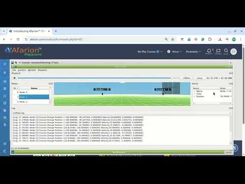
 Take Me to Afarion ns-3 iPlayground