Introduction to types of X2 Handover
Technically, there are different kinds of X2 Handover Scenarios possible in a practical LTE network.
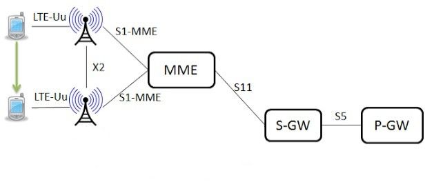
X2-based handover without SGW relocation without change in MME
We can assume an X2 handover scenario within on MME as illustrated in the following diagram.
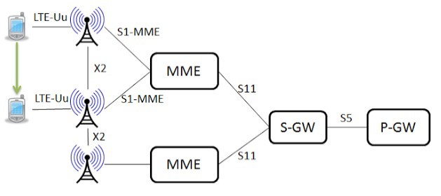
X2-based handover without SGW relocation
We can assume an X2 handover scenario within different MME within the same S-GWas illustrated in the following diagram, in that case, SGW relocation is not necessary.
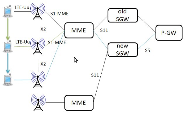
X2-based handover with SGW relocation
We can assume an X2 handover scenario within different MME within different S-GWsas illustrated in the following diagram, in that case, SGW relocation is necessary.
Under ns3, we can simulate a scenario that is like the first one in the above three because a single SGW/PGW node will be assumed in all simulation scenarios because of the present limitations of the LENA LTE/EPC module. Further, MME is simply implemented in the LTE/EPC as a logical unit providing the required functionality.
About LTE/EPC ns3 Module
LENA LTE/EPC Network Simulator allows LTE small/macrocell vendors to design and test self-organized network algorithms and solutions. LENA is based on the ns-3 network simulator. The ns-3 LTE model software library allows the simulation of LTE networks including the Evolved Packet Core (EPC). Ns-3 LTE model supports X2 crossover. That is handover between eNBs (S1 handover is not yet supported because, the scenarios with inter-SGW mobility are not of interest to the LENA project so that, a single SGW/PGW node will be present in all simulations scenarios).
About this X2 Handover Simulation
This simulation is based on the original example script “lena-x2-handover-measures.cc” – For the better visualization of the x2 handover scenario, we just added few lines in the original script to enable NetAnim logs. Even though the animation functionalities of LTE/EPC simulations are not fully supported by NetAnim, we can visualize this X2 handover scenario only using some basic, supported animation functionalities of NetAnim.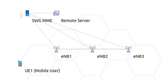
The original “lena-x2-handover-measures.cc” simulation script is for an automatic X2-based handover based on the RSRQ measures. Our modified script instantiates three eNodeB nodes, attaches one UE to the ‘source’ eNB. The UE is connected to a remote server and start applications on UEs and a remote host. The UE moves between the three eNBs, each instant, it reports measures to the serving eNB and the ‘source’ (serving) eNB triggers the handover of the UE towards the ‘target’ eNB when it considers it is a better eNB.
The Simulation Output
The following are some preliminary outputs from which we can visualize the X2 handover phenomena.
If we run the modified simulation,
$ waf –run SimpleLenaX2HandoverSimulation
It will produce the following outputs in the terminal window :
[ 926/2433] Compiling scratch/SimpleLenaX2HandoverSimulation.cc
[2406/2433] Linking build/scratch/SimpleLenaX2HandoverSimulation
Waf: Leaving directory `/home/jason/ns-allinone-3.25/ns-3.25/build’
Build commands will be stored in build/compile_commands.json
‘build’ finished successfully (5.052s)
/NodeList/5/DeviceList/0/LteUeRrc/ConnectionEstablished UE IMSI 1: connected to CellId 1 with RNTI 1
/NodeList/2/DeviceList/0/LteEnbRrc/ConnectionEstablished eNB CellId 1: successful connection of UE with IMSI 1 RNTI 1
/NodeList/2/DeviceList/0/LteEnbRrc/HandoverStart eNB CellId 1: start handover of UE with IMSI 1 RNTI 1 to CellId 2
/NodeList/5/DeviceList/0/LteUeRrc/HandoverStart UE IMSI 1: previously connected to CellId 1 with RNTI 1, doing handover to CellId 2
/NodeList/5/DeviceList/0/LteUeRrc/HandoverEndOk UE IMSI 1: successful handover to CellId 2 with RNTI 1
/NodeList/3/DeviceList/0/LteEnbRrc/HandoverEndOk eNB CellId 2: completed handover of UE with IMSI 1 RNTI 1
/NodeList/3/DeviceList/0/LteEnbRrc/HandoverStart eNB CellId 2: start handover of UE with IMSI 1 RNTI 1 to CellId 3
/NodeList/5/DeviceList/0/LteUeRrc/HandoverStart UE IMSI 1: previously connected to CellId 2 with RNTI 1, doing handover to CellId 3
/NodeList/5/DeviceList/0/LteUeRrc/HandoverEndOk UE IMSI 1: successful handover to CellId 3 with RNTI 1
/NodeList/4/DeviceList/0/LteEnbRrc/HandoverEndOk eNB CellId 3: completed handover of UE with IMSI 1 RNTI 1
jason@jason-K55VM:~/ns-allinone-3.25/ns-3.25$
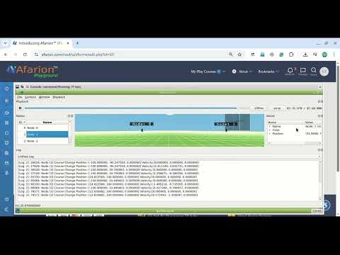
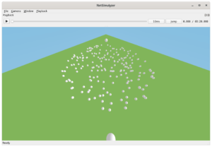
If we visualize the scenario in NetAnim, then it will show the x2 handover. You can see the packet transfer denoted by the symbol ‘<‘ and ‘ >’ between eNBs in the event of handover ( when the UE node is in the middle of two eNBs). You can play this video and visualize the X2 handover between eNBs.
Conclusion
ns3 supports X2 handover simulation with some limited functionalities. In addition to that, still, there are some bugs (as we found in ns3 discussion forums) related to X2 handover (so that you may end up with some unexpected results). Irrespective of these limitations, more Analysis of this simulation is possible by enabling the built-in trace supports such as PHY Layer Traces, MAC Layer Traces, RLC Traces, PDCP Traces etc. So that we can do a quality research simulation within these limits of this simulator.
 Take Me to Afarion ns-3 iPlayground