VANET Simulation and Visualization under ns-3
In fact, with default installation itself, ns-3 does not have rich support for simulating VANET. The reason is there is no fully functional DSRC protocol stack available in/for ns-3. Anyway, we may use wave short messaging to simulate different safety messaging features of the VANET scenario. In addition to that one may use the standard routing protocols such as AODV, DSDV etc on a prototype hypothetical VANET simulation- but they are not according to the strict DSRC standards.
The Network Visualization tool available under ns-3 (NetAnim) can not be used to visualize a typical VANET scenario in 3D. (It can able to render only 2D outputs. So that, it can not be used to visualize 3D VANET models.
NetSimulizer is a 3D Network Visualization tool written for visualizing outputs of ns-3 3D Network simulations. In the ns-3 (versions up to 3.35), there are no rich, 3D mobility models available to simulate realistic VANET mobility. So we need to use some external tools such as SUMO, Mobisim etc., to generate ns-2 mobility traces and then import them into a typical ns-3 VANET simulation. Even though a 3D visualization or even 2D visualization is not at all needed while doing scholarly research work, while learning the fundamentals of a simulation, for better understanding, all of us just want to visualize the network that we are simulating. For that, we need a better visualization of the simulated network. In addition to that, the pictorial and video outputs of the simulated network will be useful to make one understand our ideas during our project or research presentations.
Simulating VANET Mobility using Manhattan Mobility Model :
The Manhattan mobility model is a guide that leads the driver of a vehicle on the correct path. It is an urban-type of mobility model for vehicular ad-hoc networks (VANET). The Manhattan mobility model uses a “grid road topology. It works optimally where streets are situated in an organized manner. In this mobility model, mobile nodes move in the horizontal or vertical direction on an urban map. The Manhattan model employs a probabilistic approach in the selection of nodes movements since, at each intersection, a vehicle chooses to keep moving in the same direction. The probability of going straight is 0.5 and taking a left or right is 0.25 each.
The Manhattan model is not suitable for highway systems. Although this model provides flexibility for the nodes to change the direction, it imposes geographic restrictions on node mobility.
This model can be used in Vehicular Adhoc Network (VANET) Simulations and Mobile Adhoc Network (MANET) simulations.
In this simulation, I decided to use Mobisim to generate the Grid Way mobility for this VANET simulation.
The following article explains the way of using Mobisim:
VANET Mobility Trace file Generation using Mobisim for ns-2 and ns-3 Simulations
About this Mobile VANET 3D Network Simulation
In this article, we will see the way of simulating and visualizing a VANET under ns-3 using NetAnim and NetSimulyzer.
NetSimulyzer 3D visualization tool able to ‘play’ the 3D network scenario from different camera perspectives using a special trace output file (.json format) which was created during the ns-3 simulation (the simulation which uses ns-3 NetSimulyzer module).
So, the NetSimulyzer 3D visualization tool can be used to play/animate/visualize ns-3 network scenarios for better understanding, presenting and debugging them.
We can simulate realistic 3D VANET using ns3 along with NetSimulyzer. In this article, we will see the way of simulating a VANET with the “Grid way’ mobility model.
Caution: This simulation only addresses the primitive problems in simulating and visualizing a 3D VANET Simulation. There are other aspects such as setting different routing protocols and different traffic types in such VANET scenario. They are not addressed in this article. Further, there are some additional aspects needed to do a trace analysis on the simulated VANET scenario; that is also not discussed here. Further, for simulating realistic movements and orientation of 3d nodes, we have to do some modifications in the core NetSimulyzer. That is also not described here. The readers must try their own ideas for simulating such mobility.
The Components of the Simple 3D VANET ns-3 Simulation Script
The following code segment presents the important components of the ns-3 simulation script which is used to simulate our 3D VANET.
Include the header files Needed
The following lines include the necessary header files.
#include “ns3/core-module.h”
#include “ns3/mobility-module.h”
#include “ns3/ns2-mobility-helper.h”
#include “ns3/netanim-module.h”
#include “ns3/netanim-module.h”
#include “ns3/netsimulyzer-module.h”
The following two articles explain the way to set up the NetSimulyzer 3D visualization support.
Installing NetSimulyzer 3D Visualization Support Add-on Module in ns-3 under Debian/Ubuntu
Installing NetSimulyzer 3D Visualization Tool under Debian/Ubuntu
The following lines show the lines for creating some basic nodes for this VANET simulation.
// Create Mobile nodes.
NodeContainer MobileNodes;
MobileNodes.Create (30);
The following lines show the way of importing an ns-2 mobility trace for this VANET simulation.
// Create Ns2MobilityHelper with the specified trace log file as parameter
Ns2MobilityHelper ns2 = Ns2MobilityHelper (“GridWayVANET-cars30-Area1000x1000.mobility”);
// configure movements for each node, while reading trace file
ns2.Install ();
Setup NetSimulyzer Parameters
The following section of code set a 3D model of a car for our 3D VANET simulation.
auto orchestrator = CreateObject
// Use helper to define model for visualizing nodes and aggregate to Node object
netsimulyzer::NodeConfigurationHelper nodeHelper{orchestrator};
nodeHelper.Set (“Model”, netsimulyzer::models::QC_REDCAR_VALUE);
nodeHelper.Set (“Scale”, DoubleValue (1));
nodeHelper.Install(MobileNodes);
Create a Trace file and set up a car image for 2D visualization on NetAnim
AnimationInterface anim (“SimpleNS3SimulationWithMobisimFreeway-mobility-trace.xml”);
for(int i=0;i<30;i++) anim.UpdateNodeImage (i, anim.AddResource (“car-icon.png”) );
The trace file created by the above lines will be used to visualize the VANET in 2D on NetAnim.
Stop the Simulation
Simulator::Stop (Seconds (200));
Simulator::Run ();
return 0;
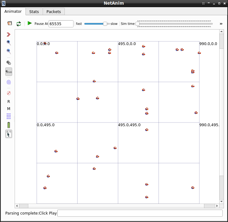
The 2D VANET Simulation output with NetAnim
The following video shows the 2D output of the VANET simulation on NetAnim.
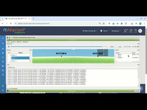
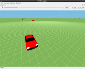
The 3D VANET Simulation output with NetSimulyzer
The following video shows the 3D output of the VANET simulation on NetSimulyzer.
Note: The visualization of Packet Transmission and wave Propagation on Medium are not yet implemented in NetSimulyzer. Further, this prototype simulation does not include any data flows and packet transmissions between cars. So we can only see the movement of nodes. But we can add “log events” to understand the events of transmission and reception through some text messages that will be displayed in a separate text window of NetSimulyzer.
The following articles, also use the 3D Visualization tool NetSimulyzer:
- Implementation of Spring Mobility Model for ns-3 and Visualizing it in 3D along with Circle Mobility
- An ns-3 Simulation to Plot Circle Mobility on Graph
The following article shows the state of the art VANET simulations using ms-van3t
The following is the typical output of ms-van3t-sumo integrated realistic VANET simulation
 Take Me to Afarion ns-3 iPlayground