Unmanned Aerial Vehicle (UAV)
Unmanned Aerial Vehicle (UAV) networks play important role in the future generations of wireless networks. Due to the high cost and failures involved in real system based tests, simulation-based studies are gaining much attention.
The Aerial Ad-hoc Network (AANET) :
The term AANET is interchangeably used to denote Aerial Ad hoc Network, Aircraft Ah hoc Network and Aeronautical Ad hoc Network. Aerial Ad hoc Network (AANET) is a particular type of three-dimensional (3D) wireless ad hoc network. And alternatively, the term FANET is used to denote a Flying Ad hoc Network in general.
The Flying Ad-hoc Network (FANET)
FANET is a self-organizing wireless network that enables inexpensive, flexible, and easy-to-deploy flying nodes, such as unmanned aerial vehicles (UAVs), to communicate among themselves in the absence of fixed network infrastructure.
Problems in simulating and visualizing 3D FANET or AANET under ns-3 :
- In the ns-3 (versions up to 3.33) , there are no rich, 3D mobility models available so that we can not simulate a practical 3D FANET or AANET by using the available components and models.
- Even though if we simulate a 3D scenario with a custom 3D mobility model, the standard visualization tool of ns-3 (NetAnim) can only show the 2D view of a 3D simulation. It makes it impractical to visualize the simulated 3D scenario.
About this 3D FANET Simulation
In this article, we will see the way of simulating and visualizing a 3D FANET or AANET under ns-3 using NetSimulyzer.
NetSimulyzer 3D visualization tool able to ‘play’ the 3D network scenario from different camera perspectives using a special trace output file (.json format) which was created during the ns-3 simulation (the simulation which uses ns-3 NetSimulyzer module).
So, the NetSimulyzer 3D visualization tool can be used to play/animate/visualize ns-3 network scenarios for better understanding, presenting and debugging them.
We can simulate realistic FANETs using ns3 along with NetSimulyzer. In this article, we will see the way of simulating a FANET of Quadcopters that are roving above the buildings.
To simplify the understanding of the 3D components of a FANET simulation, we purposely didn’t include the traffic-related components and routing related components of FANET in this simulation.
The Components of the Simple 3D FANET ns-3 Simulation Script
The following code segment presents the important components of the ns-3 simulation script which is used to simulate our 3D FANET.
The following two articles explain the way to set up the Netsimulyzer 3D visualization support.
Installing NetSimulyzer 3D Visualization Support Add-on Module in ns-3 under Debian/Ubuntu
Installing NetSimulyzer 3D Visualization Tool under Debian/Ubuntu
Installing NetSimulyzer 3D Visualization Tool under Debian/Ubuntu
Include the header files Needed
The following lines include the necessary header files. The suitable 3D mobility model should be incorporated in mobility-module.h and the Netsimulyzer ns-3 module should be installed in the ns-3 directory tree.
#include “ns3/core-module.h”
#include “ns3/mobility-module.h”
#include “ns3/netanim-module.h”
#include “ns3/netsimulyzer-module.h”
Simulate some 3D buildings on Ground
// create a some buildings
double buildingSizeX = 100; // m
double buildingSizeY = 50; // m
double streetWidth = 25; // m
double buildingHeight = 10; // m
uint32_t numBuildingsX = 10;
uint32_t numBuildingsY = 10;
std::vector
for (uint32_t buildingIdX = 0; buildingIdX < numBuildingsX; ++buildingIdX)
{
for (uint32_t buildingIdY = 0; buildingIdY < numBuildingsY; ++buildingIdY)
{
Ptr < Building > building;
building = CreateObject
building->SetBoundaries (Box (buildingIdX * (buildingSizeX + streetWidth),
buildingIdX * (buildingSizeX + streetWidth) + buildingSizeX,
buildingIdY * (buildingSizeY + streetWidth),
buildingIdY * (buildingSizeY + streetWidth) + buildingSizeY,
0.0, buildingHeight));
building->SetNRoomsX (1);
building->SetNRoomsY (1);
building->SetNFloors (1);
buildingVector.push_back (building);
}
}
Create Some Drone Nodes and install RandomWalk3dMobilityModel in them
NodeContainer drones;
sta.Create (10);
MobilityHelper mobility;
mobility.SetMobilityModel (“ns3::RandomWalk3dMobilityModel”,
“Mode”, StringValue (“Time”),
“Time”, StringValue (“10s”),
“Speed”, StringValue (“ns3::ConstantRandomVariable[Constant=25.0]”),
“Bounds”, BoxValue (Box (0.0, 300.0, 0.0, 300.0, 0.0, 200.0)));
mobility.Install (drones);
Configure Things for 3D Netsimulyzer Visualization
The following are the three important things that will be done by this section of code:
- The 3D simulation output will be stored in the file “SimpleNS3FANETRandomWalk3D.json”.
- A Quadcopter Drone 3D model will be set to all the FANET nodes.
- The 3D buildings will be created using the previously configured buildings information
Configure standard NetAnim file and end the simulation
For comparison purposes, we create a NetAnim simulation file, which will only be capable of showing 2D of this 3D scenario.
AnimationInterface anim (“SimpleNS3RandomWalk3D.xml”);
Simulator::Stop (Seconds (simTimeSec));
Simulator::Run ();
Simulator::Destroy ();
return 0;
The 2D output of the Simulation using NetAnim
The following output shows the output of FANET simulation on NetAnim. A 3D scene that is rendered on a 2D canvas will be similar to the following output.
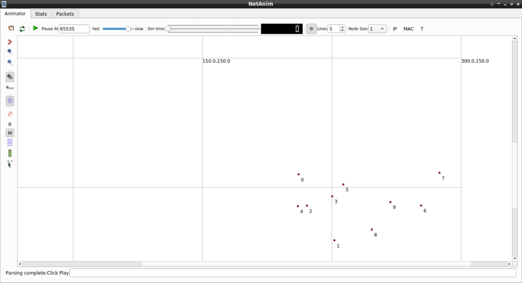
The following video shows the 2D animation of the 3D FANET scenario.
The 3D Visualization using NetSimulyzer Tool
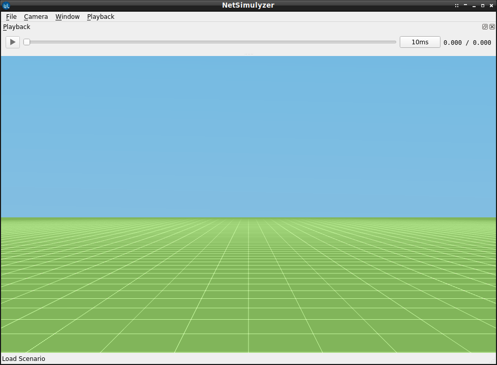
The following output shows the NetSimulyzer GUI on initialization(before loading our FANET simulation).
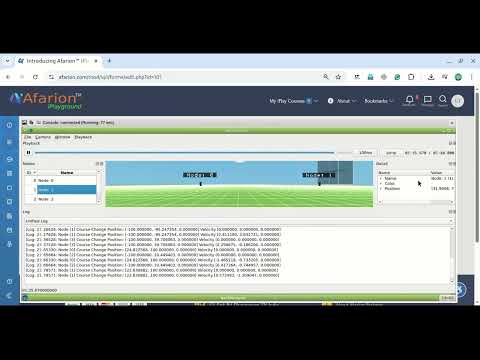
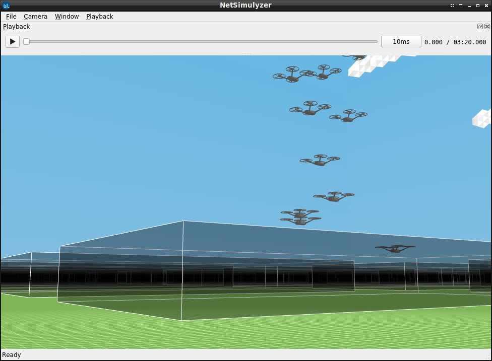
The following output shows the NetSimulyzer GUI after loading our FANET simulation.
The 3D Simulation output with NetSimulyzer
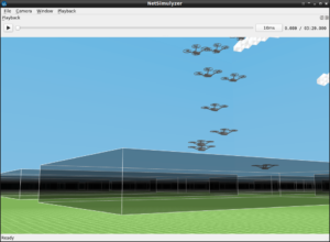
The following video shows the 3D output of the simulation on NetSimulyzer.
Note:
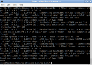
The visualization of Packet Transmission and wave Propagation on Medium is not yet implemented in NetSimulyzer. So we can only see the movement of nodes. But we can add “log events” to understand the events of transmission and reception through some text messages that will be displayed in a separate text window of NetSimulyzer.
The following articles present more FANET simulations :
- Implementation of Spring Mobility Model for ns-3 and Visualizing it in 3D along with Circle Mobility
- Simulation of Multi-Tire UAV/AANET/FANET Topology Using Gauss-Markov 3D Mobility Model Under ns-3
References:
 Take Me to Afarion ns-3 iPlayground