Aquatic Animal Tracking: 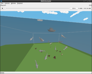
Tracking marine animals can be extremely tricky due to GPS signals not functioning well underwater[1]. Underwater acoustic communication is a technique of sending and receiving messages below water.
There are several ways of employing such communication but the most common is by using hydrophones. Underwater communication is difficult due to factors such as multi-path propagation, time variations of the channel, small available bandwidth and strong signal attenuation, especially over long ranges.
Compared to terrestrial communication, underwater communication has low data rates because it uses acoustic waves instead of electromagnetic waves.
Acoustic communications are the typical physical layer technology in UWSNs as other mediums are not feasible to be used in the underwater environment, such as radio waves and optical waves.
Each of these sensor nodes is equipped with an acoustic modem and being deployed manually or randomly in deep or shallow water based on their application requirement. However, there are several limitations and challenges in UWSNs because of the uniqueness of UWSNs compared to other networking environments like Terrestrial Wireless Sensor Networks (TWSNs)
Challenges for Aquatic Animal Tracking
In [1], some of the following challenges of aquatic animal tracking has been presented :
Terrestrial animal tracking systems, we can leverage GPS for location data and satellites for collecting that data over broad geographies. But we can not use GPS in underwater scenarios.
Unlike the normal surface animal tracking scenario, there are practical complexities of attaching a tag to a given animal under water.
Due to the size and weight of tracking devices, they can only be used on larger animals.
UAN/UWSN Simulation and Visualization support in/for ns-3
In fact, with default installation itself, ns-3 does have the physical layer and mac layer for simulating acoustic underwater communications (UAN Framework). The main goal of the UAN Framework is to enable researchers to model a variety of underwater network scenarios. The ns-3’s UAN model is broken into four main parts: The channel, PHY, MAC and Autonomous Underwater Vehicle (AUV) models. But the default UAN framework of ns-3 only contains some basic functionalities and does not contain any UWSN routing protocols.
Another underwater protocol extension is also available for ns-3. It is called ‘Aqua-Sim Next Generation’ (AquaSim-NG). It was originally developed for ns-2 and then ported to ns-3. The ns-2 version of aquasim has a separate 3D visualization tool called ‘Aqua3D’. But we can not use that 3D visualization tool Aqua3D to visualize ns-3 network scenarios.
The Network Visualization tool available under ns-3 (NetAnim) can not be used to visualize 3D underwater network scenarios. (It can able to render only 2D output of a 3D simulation. So that, it can not be used to visualize a 3D UAN/UWSN simulation output.
NetSimulizer is a 3D Network Visualization tool written for visualizing outputs of ns-3 3D Network simulations.
Problems in simulating and visualizing 3D Mobile UAN/UWSN under ns-3 :
- In the ns-3 (versions up to 3.33) , there are no rich, 3D mobility models available so that we can not simulate a practical 3D UAN/UWSN by using the available components and models.
- Even though if we simulate a 3D scenario with a custom 3D mobility model, the standard visualization tool of ns-3 (NetAnim) can only show the 2D view of a 3D simulation. It makes it impractical to visualize the simulated 3D scenario.
About this Mobile Underwater 3D Network Simulation
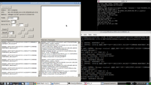
In this article, we will see the way of simulating and visualizing a UAN/UWSN under ns-3 using NetSimulyzer.
NetSimulyzer 3D visualization tool able to ‘play’ the 3D network scenario from different camera perspectives using a special trace output file (.json format) which was created during the ns-3 simulation (the simulation which uses ns-3 NetSimulyzer module).
So, the NetSimulyzer 3D visualization tool can be used to play/animate/visualize ns-3 network scenarios for better understanding, presenting and debugging them.
We can simulate realistic UAN/UWSN using ns3 along with NetSimulyzer. In this article, we will see the way of simulating a UWSN composing of some underwater mobile sensor nodes and a sink node (Boat) at the surface of the water.
In this simulation, I decided to use AquaSim-NG to simulate a realistic, Mobile Underwater Sensor Network.
Note:
This simulation only addresses the primitive problems in simulating and visualizing a 3D Aquatic Animal Tracking UWSN Simulation. There are other aspects such as setting different routing protocols and different traffic types in such UWSN scenario. They are not addressed in this article. Further, there are some additional aspects needed to do a trace analysis on the simulated UWSN scenario; that are also not discussed here. Further, for simulating realistic movements and orientation of 3d nodes, we have to do some modifications in the core Netsimulyzer. That is also not described here. The users must try their own ideas for simulating such mobility.
The Components of the Simple 3D UWSN ns-3 Simulation Script
The following code segment presents the important components of the ns-3 simulation script which is used to simulate our 3D UWSN.
Include the header files Needed
The following lines include the necessary header files. The suitable 3D mobility model should be incorporated in mobility-module.h and the Netsimulyzer ns-3 module should be installed in the ns-3 directory tree. The header file for aqua-sim-ng and other header files for required components are included.
#include “ns3/core-module.h”
#include “ns3/network-module.h”
#include “ns3/aqua-sim-ng-module.h”
#include “ns3/applications-module.h”
#include “ns3/log.h”
#include “ns3/callback.h”
#include “ns3/mobility-module.h”
#include “ns3/netanim-module.h”
#include “ns3/netsimulyzer-module.h”
The following two articles explain the way to set up the Netsimulyzer 3D visualization support.
Installing NetSimulyzer 3D Visualization Support Add-on Module in ns-3 under Debian/Ubuntu
Installing NetSimulyzer 3D Visualization Tool under Debian/Ubuntu
The following lines show some of the parameters that we used for creating different nodes and setting their communication attributes for this underwater network simulation.
double simStop = 20; //seconds
uint32_t noShark = 10;
uint32_t noTurtles = 10;
uint32_t m_dataRate = 10000;
uint32_t m_packetSize = 40;
double range = 100;
NodeContainer SharkCon;
NodeContainer TurtlesCon;
NodeContainer sinksCon;
NodeContainer senderCon;
SharkCon.Create(noShark);
TurtlesCon.Create(noTurtles);
sinksCon.Create(1);
senderCon.Create(1);
PacketSocketHelper socketHelper;
socketHelper.Install(SharkCon);
socketHelper.Install(TurtlesCon);
socketHelper.Install(sinksCon);
socketHelper.Install(senderCon);
Simulate some 3D Ocean Water Body top of the Ocean Ground
The following section of code will mimic some water body for our UWSN. (This will not affect the Physical Media Implementation of AquaSim NG – it is just for 3D visualization on NetSimulyzer only.
// create a some Water Body
double WaterSizeX = 500; // m
double WaterSizeY = 500; // m
double WaterHeight = 250; // m
std::vector
Ptr < Building > Water;
Water = CreateObject
Water->SetBoundaries (Box (0,
WaterSizeX,
0,
WaterSizeY,
0.0, WaterHeight));
Water->SetNRoomsX (1);
Water->SetNRoomsY (1);
Water->SetNFloors (1);
WaterVector.push_back (Water);
Create Some Mobile Underwater Sensor Nodes that were attached on Sharks and Trutles and install RandomWalk3dMobilityModel them
/*
* Preset up mobility model for nodes and sinks here
*/
MobilityHelper mobility;
mobility.SetMobilityModel (“ns3::GaussMarkovMobilityModel”,
“Bounds”, BoxValue (Box (0, 300, 0, 300, 20, 200)),
“TimeStep”, TimeValue (Seconds (0.5)),
“Alpha”, DoubleValue (0.85),
“MeanVelocity”, StringValue (“ns3::UniformRandomVariable[Min=0|Max=10]”),
“MeanDirection”, StringValue (“ns3::UniformRandomVariable[Min=0|Max=6.283185307]”),
“MeanPitch”, StringValue (“ns3::UniformRandomVariable[Min=0.05|Max=0.5]”),
“NormalVelocity”, StringValue (“ns3::NormalRandomVariable[Mean=10.0|Variance=5.0|Bound=10.0]”),
“NormalDirection”, StringValue (“ns3::NormalRandomVariable[Mean=0.0|Variance=0.2|Bound=0.4]”),
“NormalPitch”, StringValue (“ns3::NormalRandomVariable[Mean=0.0|Variance=0.02|Bound=0.04]”));
mobility.Install (SharkCon);
mobility.Install (senderCon);
MobilityHelper mobilityTurtle;
mobilityTurtle.SetMobilityModel (“ns3::GaussMarkovMobilityModel”,
“Bounds”, BoxValue (Box (0, 300, 0, 300, 20, 70)),
“TimeStep”, TimeValue (Seconds (0.5)),
“Alpha”, DoubleValue (0.85),
“MeanVelocity”, StringValue (“ns3::UniformRandomVariable[Min=0|Max=1]”),
“MeanDirection”, StringValue (“ns3::UniformRandomVariable[Min=0|Max=6.283185307]”),
“MeanPitch”, StringValue (“ns3::UniformRandomVariable[Min=0.05|Max=0.5]”),
“NormalVelocity”, StringValue (“ns3::NormalRandomVariable[Mean=1.0|Variance=5.0|Bound=1.0]”),
“NormalDirection”, StringValue (“ns3::NormalRandomVariable[Mean=0.0|Variance=0.2|Bound=0.4]”),
“NormalPitch”, StringValue (“ns3::NormalRandomVariable[Mean=0.0|Variance=0.02|Bound=0.04]”));
mobilityTurtle.SetPositionAllocator (“ns3::RandomBoxPositionAllocator”,
“X”, StringValue (“ns3::UniformRandomVariable[Min=00.0|Max=300.0]”),
“Y”, StringValue (“ns3::UniformRandomVariable[Min=00.0|Max=300.0]”),
“Z”, StringValue (“ns3::UniformRandomVariable[Min=20.0|Max=70.0]”));
mobilityTurtle.Install (TurtlesCon);
Create a Sink Node and install ConstantPositionMobilityModel in it
MobilityHelper otherMobility;
//Set sink at origin and surround with uniform distribution of regular nodes.
otherMobility.SetPositionAllocator(position);
otherMobility.SetMobilityModel(“ns3::ConstantPositionMobilityModel”);
otherMobility.Install(sinksCon);
otherMobility.Install(senderCon);
Configure Things for 3D Netsimulyzer Visualization
The following are the three important things that will be done by this section of code:
- The 3D simulation output will be stored in the file “AquaticAnimalTracking-NS3UWSNGaussMarkovMobilityModel3D.json”.
- Underwater sensors nodes will be represented by a 3D Sphere models.
- The Sink Node will be represented by a 3d Boat object on the Water Surface
- 3D water body will be created using the previosuly configured information
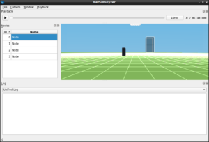
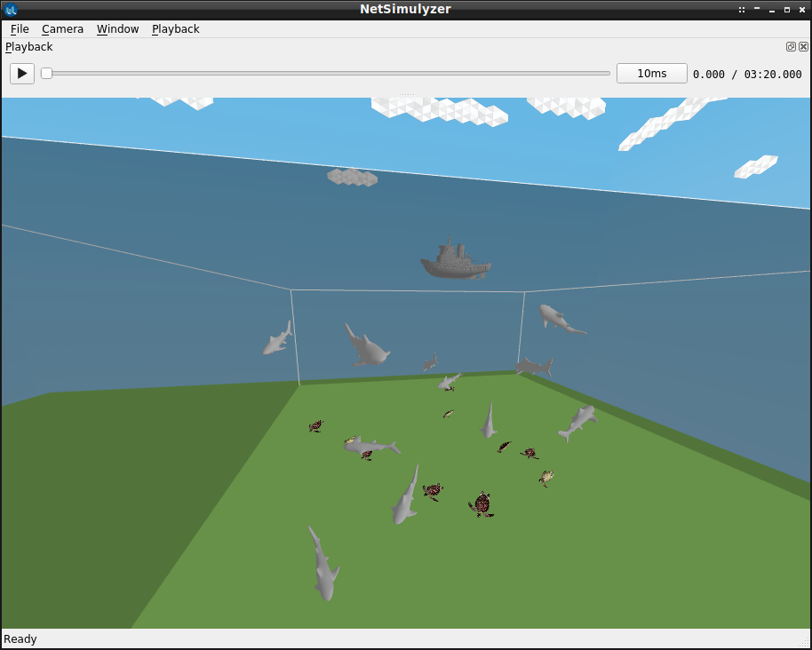
A view of the network from the bottom. (see the bottom surface of the boat which is on the surface of the water). The long white objects are simulated clouds in the sky. You can see the simulated tiger sharks and turtles that were roaming under the water.
Configure standard NetAnim file and end the simulation
For comparison purposes, we create a NetAnim simulation file, which will only be capable of showing 2D of this 3D Mobile UWSN scenario.
AnimationInterface anim (“AquaticAnimalTracking-NS3UWSNGaussMarkovMobilityModel3D.xml”);
Simulator::Stop (Seconds (simTimeSec));
Simulator::Run ();
Simulator::Destroy ();
The 3D Aquatic Animal TrackingUWSN Simulation output with NetSimulyzer
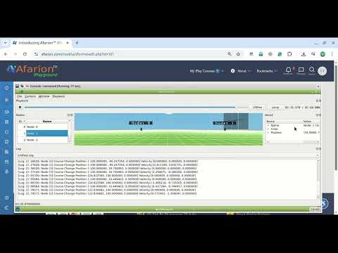
The following video shows the 3D output of the Mobile UWSN simulation on NetSimulyzer.
Final Note:
The visualization of Packet Transmission and wave Propagation on Medium are not yet implemented in NetSimulyzer. So we can only see the movement of nodes. But we can add “log events” to understand the events of transmission and reception through some text messages that will be displayed in a separate text window of NetSimulyzer.
You may see a few more UWSN simulation examples here:
- Simulating And Visualizing 3D Mobile Underwater Sensor Network (UWSN) Under ns-3
- Implementation of Circle Mobility Model for ns-3 and Visualizing it in 3D
 Take Me to Afarion ns-3 iPlayground