Simulation of Simple 3D FANET with TCP flows under ns-3
In this example, we simulate TCP flows in a FANET scenario, but the same idea can be implemented on a MANET or VANET or WSN and other scenarios also. This simulation is little bit modified version of our previous simulation that you may find at the following link:
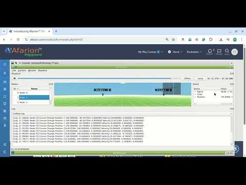
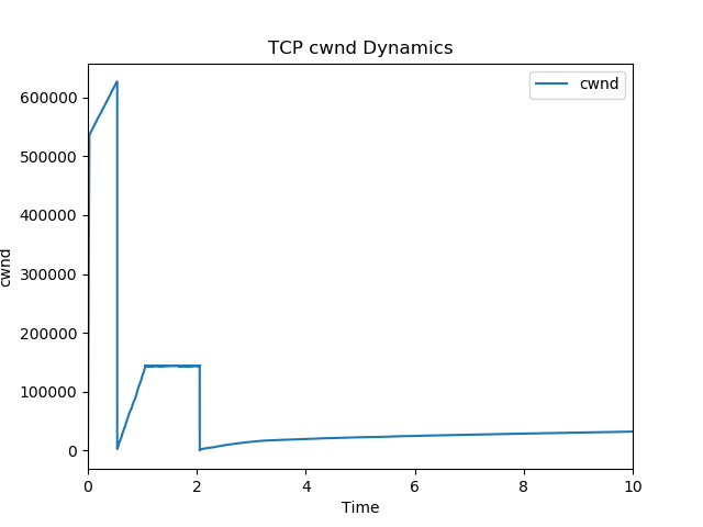
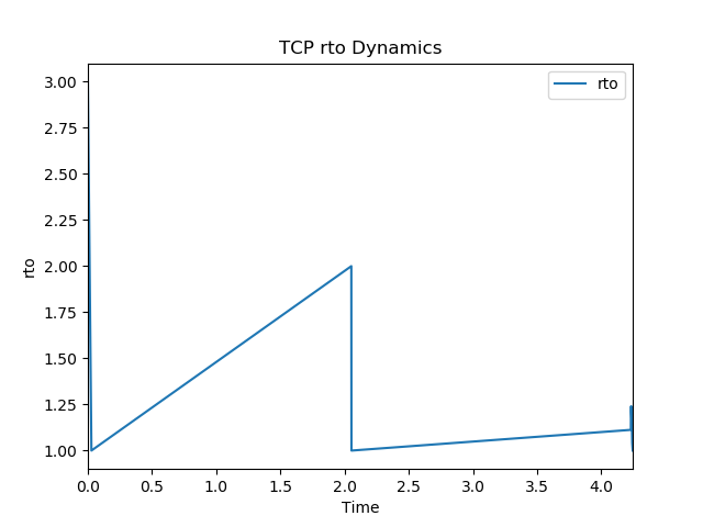
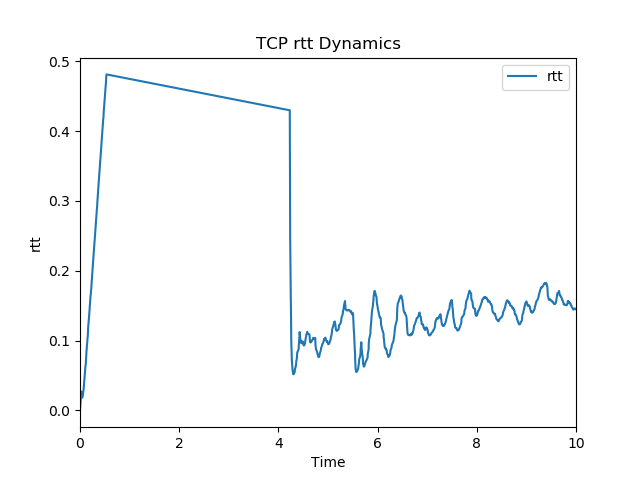
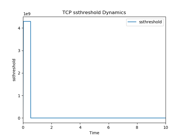
Real-time Visualization of TCP cwnd, rtt, rto and ssthreshold Dynamics of a 3D FANET Scenario
This is only a prototype simulation to make one to understand the TCP dynamics with some visualization. But a practical analysis will need more nodes and more cross-traffic to really understand the change in behaviour of TCP. To study the fairness of different TCP flows and congestion mechanisms, a more suitable “bottleneck” scenario such as “Dumbbell scenario” should be used. More ideas for extensive analysis is given at the end of this article.
TCP Congestion Control Algorithms available under ns-3.
In this simulation, we used only TcpWestwood as the TCP congestion control algorithm but it is possible to use the following algorithms in this simulation.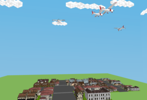
- Tcp NewReno,
- Tcp CUBIC,
- Tcp Linux Reno,
- Tcp HighSpeed,
- Tcp Hybla,
- Tcp Vegas,
- Tcp Scalable,
- Tcp Veno,
- Tcp BIC,
- Tcp YeAH,
- Tcp Illinois,
- H-TCP,
- Tcp LEDBAT,
- TCP-LP,
- Data Center TCP (DCTCP)
- and , Tcp BBR
Important Code Segments of the Proposed Simulation
The following code segment presents the important components of the ns-3 simulation script which is used to simulate and demonstrate the real-time visualization of TCP dynamics along with the 3D FANET simulation itself. In this simulation, four aeroplane nodes will use the circle mobility model and we can simulate TCP flows between them. (or between the aeroplanes and a node at the ground station).
Include the header files Needed
The following lines include the necessary header files. The Netsimulyzer ns-3 module should be installed in the ns-3 directory tree.
#include “ns3/core-module.h”
#include “ns3/network-module.h”
#include “ns3/applications-module.h”
#include “ns3/log.h”
#include “ns3/callback.h”
#include “ns3/mobility-module.h”
#include “ns3/netanim-module.h”
#include “ns3/netsimulyzer-module.h”
#include “ns3/internet-module.h”
#include “ns3/flow-monitor-module.h”
#include “ns3/config-store-module.h”
#include “ns3/wifi-module.h”
#include “ns3/aodv-module.h”
#include “ns3/dsdv-helper.h”
#include “ns3/dsr-module.h”
#include “ns3/olsr-module.h”
#include
The following lines show the creation of nodes for this FANET network simulation and setting up the communicaiton channel in it.
///////////////////////// Creating the FANET ///////////////////////////////////////// NodeContainer CirclesUAV; std::cout<<“nsetting the Wifi Phy and channel parametersn”; WifiHelper wifi; std::cout<<“tsetting up the Yans Wifi Channel in the WifiPhy Devicen”; YansWifiChannelHelper wifiChannel; wifiChannel.SetPropagationDelay (“ns3::ConstantSpeedPropagationDelayModel”); wifiPhy.Set (“RxGain”, DoubleValue (0.0)); std::cout<<“tSetting up the Wifi Adhoc Macn”; WifiMacHelper wifiMac;
std::cout<<“nCreating “<
CirclesUAV.Create (NoFanetNodes);
NetDeviceContainer allDevices;
wifi.SetStandard (WIFI_PHY_STANDARD_80211b);
YansWifiPhyHelper wifiPhy = YansWifiPhyHelper::Default ();
wifiChannel.AddPropagationLoss (“ns3::RangePropagationLossModel”, “MaxRange”, DoubleValue (txpDistance));
wifiPhy.SetChannel (wifiChannel.Create ());
wifiPhy.Set (“RxNoiseFigure”, DoubleValue (0.0));
wifiPhy.Set (“EnergyDetectionThreshold”, DoubleValue (-110.0));
wifiPhy.Set (“CcaMode1Threshold”, DoubleValue (-110.0));
wifi.SetRemoteStationManager (“ns3::ConstantRateWifiManager”, “DataMode”, StringValue (dataMode), “ControlMode”, StringValue (phyMode));
wifiMac.SetType (“ns3::AdhocWifiMac”);
allDevices = wifi.Install (wifiPhy, wifiMac, CirclesUAV);
Simulate Circle Mobility in nodes
The following section of code will do the important part of adding mobility model in the FANET nodes. We setup CircleMobilityModel in the four FANET nodes.
My previous article “Implementation of Circle Mobility Model for ns-3 and Visualizing it in 3D” shows the way of implementing CircleMobility Model.
///////////////////////// Setting Mobility Model /////////////////////////////////////////
std::cout<<“nSetting Mobility Parametersn”;
MobilityHelper CircleMobility;
MobilityHelper mobility;
CircleMobility.SetPositionAllocator (“ns3::RandomBoxPositionAllocator”,
“X”, StringValue (“ns3::UniformRandomVariable[Min=200.0|Max=250.0]”),
“Y”, StringValue (“ns3::UniformRandomVariable[Min=200.0|Max=250.0]”),
“Z”, StringValue (“ns3::UniformRandomVariable[Min=0.0|Max=250.0]”));
CircleMobility.SetMobilityModel (“ns3::CircleMobilityModel”);
CircleMobility.Install (CirclesUAV);
CirclesUAV.Get (0)->GetObject
CirclesUAV.Get (1)->GetObject
CirclesUAV.Get (2)->GetObject
CirclesUAV.Get (3)->GetObject
Installing Routing Protocol And Internet Stack in the Simulated FANET nodes
///////////////////////// Installing Routing Protocol And Internet Stack /////////////////////////////////////////
InternetStackHelper internet;
AodvHelper aodv;
internet.SetRoutingHelper (aodv);
internet.Install (CirclesUAV);
std::cout<<“Assigning ip address To Nodesn”;
Ipv4AddressHelper address;
address.SetBase (“10.1.1.0”, “255.255.255.0”);
Ipv4InterfaceContainer allInterfaces;
allInterfaces = address.Assign (allDevices);
Setting FTP Flows in the Simulated FANET nodes
///////////////////////// Setting FTP Flows /////////////////////////////////////////
Address sinkLocalAddress (InetSocketAddress (Ipv4Address::GetAny (), TcpPort));
PacketSinkHelper sinkHelper (“ns3::TcpSocketFactory”, sinkLocalAddress);
sinkHelper.SetAttribute (“Protocol”, TypeIdValue (TcpSocketFactory::GetTypeId ()));
for (uint32_t i = 0; i < NoTcpFlows; ++i)
{
// Create a FTP Application and install it on one node
BulkSendHelper sourceFTP (“ns3::TcpSocketFactory”, InetSocketAddress (allInterfaces.GetAddress (i ), FtpPort));
sourceFTP.SetAttribute (“MaxBytes”, UintegerValue (FtpPayloadSize));
ApplicationContainer sourceAppsFTP = sourceFTP.Install (CirclesUAV.Get (i+ NoFanetNodes – NoTcpFlows));
sourceAppsFTP.Start (Seconds (TcpFlowStartTime));
sourceAppsFTP.Stop (Seconds (TotalSimulationTime));
// Create a PacketSinkApplication and install it on another node
PacketSinkHelper sink (“ns3::TcpSocketFactory”, InetSocketAddress (Ipv4Address::GetAny (), FtpPort));
ApplicationContainer sinkAppsFTP = sink.Install (CirclesUAV.Get (i ));
sinkAppsFTP.Start (Seconds (TcpFlowStartTime));
sinkAppsFTP.Stop (Seconds (TotalSimulationTime));
}
Specify the Trace output Files and Schedule Recording Events for them.
std::cout << “Setting up Tcp Dynamics Tracingn”;
std::cout << “t” << MobilityScenarioFileNamePrefix << TraceFileNamePrefix << “-cwnd.datn”;
std::cout << “t” << MobilityScenarioFileNamePrefix << TraceFileNamePrefix << “-rtt.datn”;
std::cout << “t” << MobilityScenarioFileNamePrefix << TraceFileNamePrefix << “-rto.datn”;
std::cout << “t” << MobilityScenarioFileNamePrefix << TraceFileNamePrefix << “-ssth.datn”;
Simulator::Schedule (Seconds (0.00001), &TraceCwnd, MobilityScenarioFileNamePrefix + TraceFileNamePrefix + “-cwnd.dat”);
Simulator::Schedule (Seconds (0.00001), &TraceRtt, MobilityScenarioFileNamePrefix + TraceFileNamePrefix + “-rtt.dat”);
Simulator::Schedule (Seconds (0.00001), &TraceRto, MobilityScenarioFileNamePrefix + TraceFileNamePrefix + “-rto.dat”);
Simulator::Schedule (Seconds (0.00001), &TraceSsThresh, MobilityScenarioFileNamePrefix + TraceFileNamePrefix + “-ssth.dat”);
Specify the output File and Set 3D model for the Simulated FANET nodes
auto orchestrator = CreateObject
// Use helper to define model for visualizing nodes and aggregate to Node object
netsimulyzer::NodeConfigurationHelper CirclesUAVHelper{orchestrator};
SpringUAVHelper.Set (“Model”, netsimulyzer::models::QC_DRONE1_VALUE);
CirclesUAVHelper.Install(CirclesUAV);
Specify the output File and Set 3D model for the Simulated FANET nodes
auto orchestrator = CreateObject
// Use helper to define model for visualizing nodes and aggregate to Node object
netsimulyzer::NodeConfigurationHelper CirclesUAVHelper{orchestrator};
CirclesUAVHelper.Set (“Model”, netsimulyzer::models::QC_AIRPLANE_VALUE);
CirclesUAVHelper.Install(CirclesUAV);
Add 3D Model of House as a Ground Decoration
auto decoration1 = CreateObject
decoration1->SetAttribute (“Model”, StringValue(“HouseAndRoad.obj”));
decoration1->SetPosition ({0,0,0});
The Callback Functions Used to Store TCP Dynomics
The TCP Dynamics Graphs
The following graphs were prepared from the data that was logged with custom call back functions during the run of the simulation. The graphs were plotted using a custom made python script.
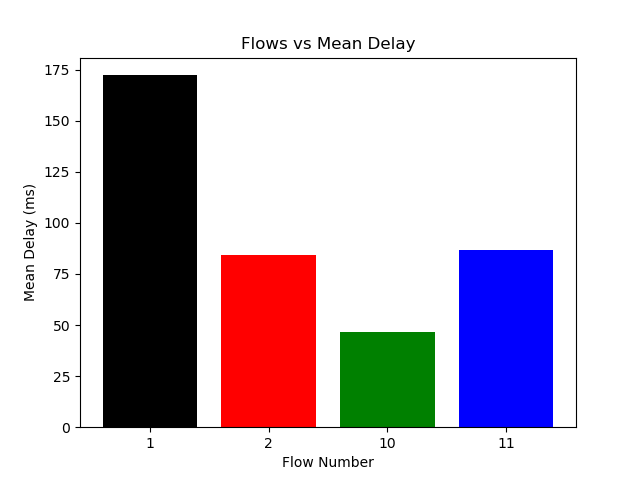
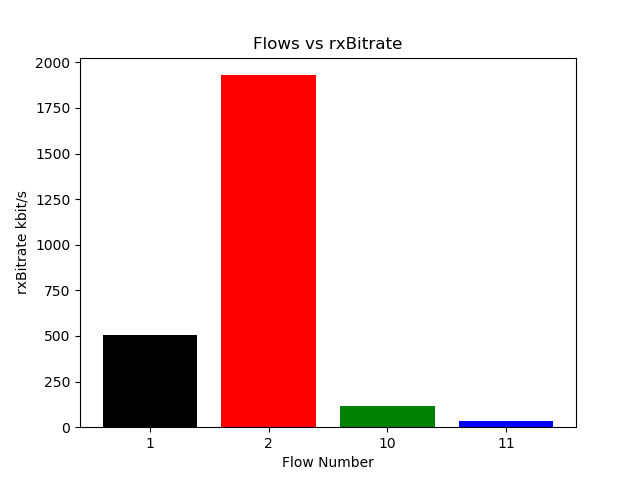
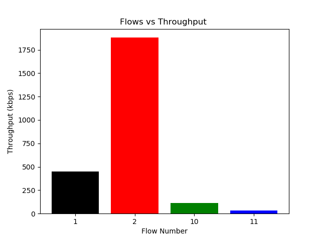
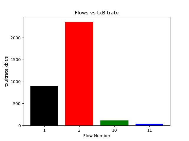
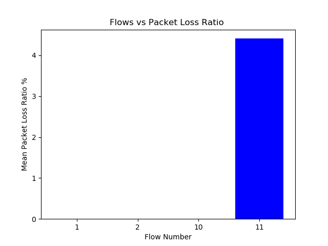
TCP flow-wise Statistics
The following graphs were prepared as saved XML file of the the ns-3 flow monitor. The XML file was parsed using a custom made python script.
Infinite Possibilities of Doing Research on FANET, MANET, VANET, WSN, WBAN and other technologies
The simulation explained above is an elementary simulation with elementary outputs. But it is possible to do an extensive simulation and analysis and produce research quality outputs.
We can study the performance of TCP under different network technologies such as FANET, MANET, VANET, WSN, WBAN and others. For this, we have to create separate topologies by adopting the communication standards of the technologies under consideration (we have to set layer functionalities of Phy, MAC, Network, Transport etc., with respect to the network in consideration).
It is possible to generate more graphs by running the simulation with different parameters and doing an extensive trace analysis on generated trace files of bach run of ns-3 simulations; This can be done by changing parameters like
(Changing Parameters)
- For Different TCP Congestion Control Algorithms (Tcp NewReno,Tcp CUBIC,Tcp Linux Reno,Tcp HighSpeed,Tcp Hybla,Tcp Vegas,Tcp Scalable,Tcp Veno,Tcp BIC,Tcp YeAH,Tcp Illinois,H-TCP,Tcp LEDBAT,TCP-LP,Data Center TCP (DCTCP)and , Tcp BBR)
- Different Network Densities (Number of nodes as 10, 20, 30, 40,.. etc.,)
- Different node Mobilities (Node Speeds : 5m/s ,10m/s, 15m/s,.. etc.,)
- Different Number of TCP flows (Flows : 2, 4, 6, 8, 10,…. etc.,)
- Different Number of UDP and other flows as cross-traffic (Flows : 2, 4, 6, 8, 10,…. etc.,)
- By changing Routing Protocols (AODV, DSDV, DSR, OLSR, etc.,)
- For changing TxPower/TxRange of the nodes (Like 100m, 200m, 300m etc.,)
- etc.,
- etc.,
We can do more analysis using the following graphs :
- Changing Parameters vs Throughput
- Changing Parameters vs Delay
- Changing Parameters vs Routing Load,
- Changing Parameters vs Netwrok Load,
- Changing Parameters vs MAC Load,
- Changing Parameters vs E2E delay,
- Changing Parameters vs PDF
- etc.,
- etc.,
So there are infinite possibilities to do a simulation and analysis. One should design their simulation and analysis according to their research requirements.
The following article explains the way of generating Genuine, Quality Outputs for a Research Publication
Generating Genuine, Quality Tables & Graphs for Publication.
 Take Me to Afarion ns-3 iPlayground