Of course, it is a very late tutorial for ns-2. But I wish to post this tutorial because, even after the official closure of the development activity on ns-2, still a lot of students and research scholars using ns-2 for their projects and research works. People still use ns-2 because of the rich availability of several protocols and applications that are implemented to cover a lot of research areas of the Network.
In fact, this tutorial will not explain each and every line of the example simulations scripts. But it will present all the examples with only a few lines of code and give you an impression that how simple and small ns-2 is. Most of the examples that you see on the internet may do the same work with a considerably large number of lines. As a custom, a lot of declaration lines are written in every simulation script that simply makes that script a huge one. In my examples, I avoided that approach.
What is ns-2
It is an open-source, event-driven simulator designed to do network-related experiments in a virtual manner. You may see lots of such “introductions” to ns-2.
From a programming/execution point of view, what is ns-2?.
I can simply say, “ns-2 is nothing but an extended version of a normal tcl scripting language with some added functionalities related to networking.
Specifically saying, ns-2 is a “special version” of tcl which has extended with some add-on tcl classes/objects and (most importantly) with some add-on C++ classes/object. By using those special c++ classes/objects and tcl classes/objects we can design a network simulation using this modified version of tcl code(ns-2 simulation script).
So an ns-2 simulation script is nothing but a tcl code (which will use some special c++ and tcl classes/objects to simulate the network)
ns-2 is nothing but Tcl – A simple proof
You may follow my procedure that you may see at the following link or any procedure to install the final version of ns-2 (ns-2.35)
Installing ns2.35(ns-allinone-2.35) Under Debian chroot Jail
So, before doing this test confirm that your system has ns-2 installed and has normal tcl installed. (in fact, ns-allinone-2.35 itself comes with a version of tcl). And confirm that the ns-2 binary “ns”, as well as the shell “tcl”, are in the system path. Open two terminal windows and issue the command ‘tcl’ in one window and the command ‘ns’ in another window.
Issue command ‘tcl’ in Terminal 1:
%
Issue command ‘ns’ Terminal 2:
%
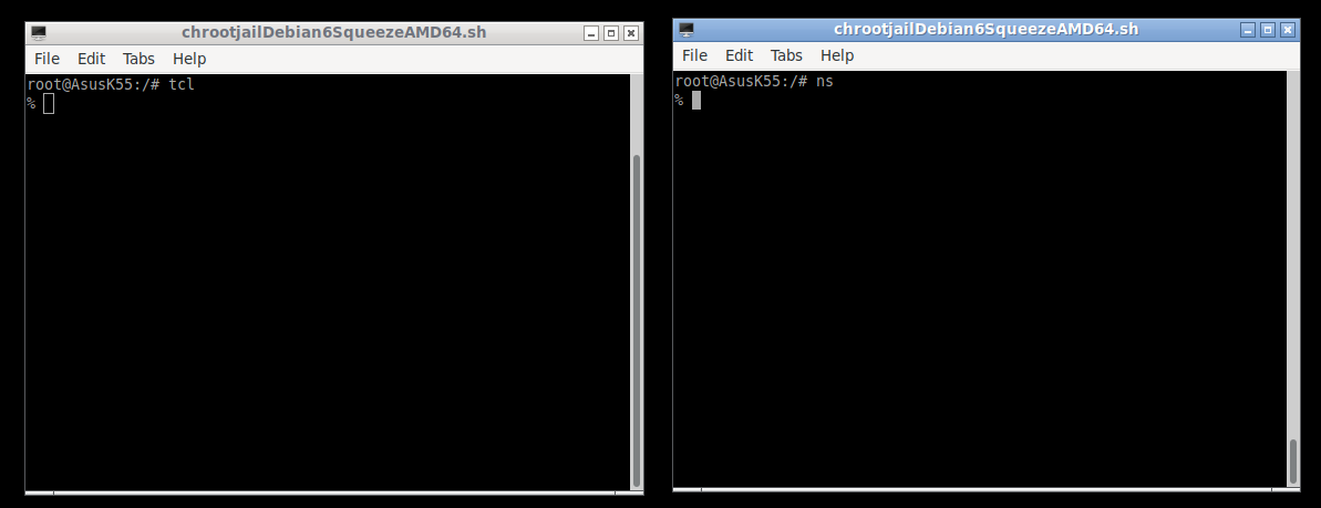
Yes. Both are showing the % prompt (of tcl).
Let us test a tcl command on both the terminals
Issue command ‘puts “Welcome” ‘ in Terminal 1:
% puts “Welcome”
Issue command ‘puts “Welcome” ‘ in Terminal 2:
% puts “Welcome”
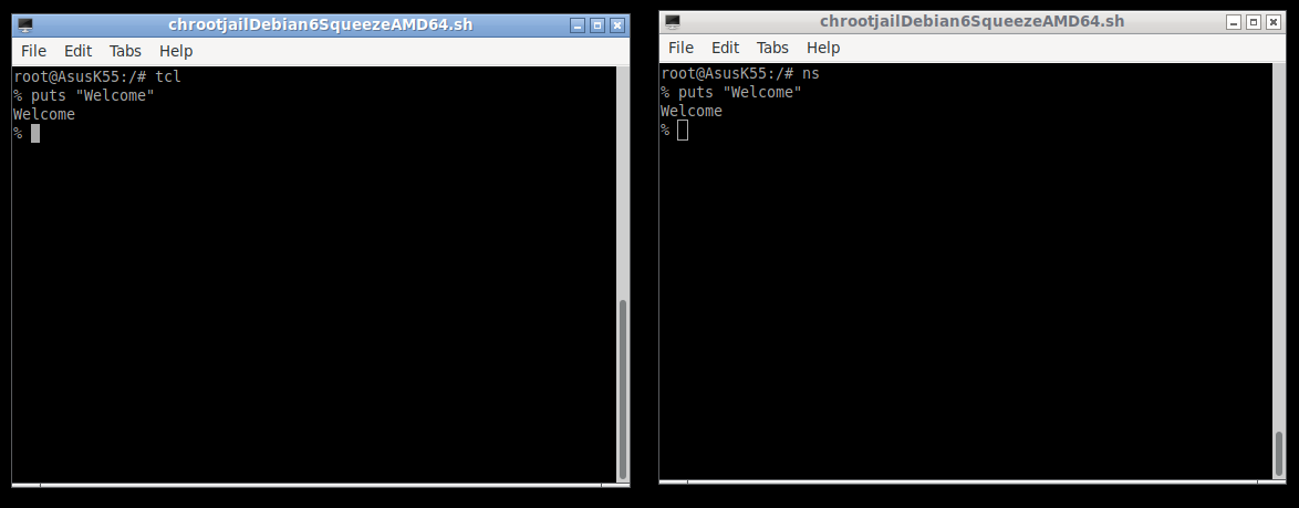
The output of the command is the same in the two terminals – because both are “tcl” only.
And for your information, you just completed your first ns2 simulation. ( )
To understand these two terminals are running different ‘tcl’s, issue a wrong command at both of the terminals. Here, our wrong command is just “a”
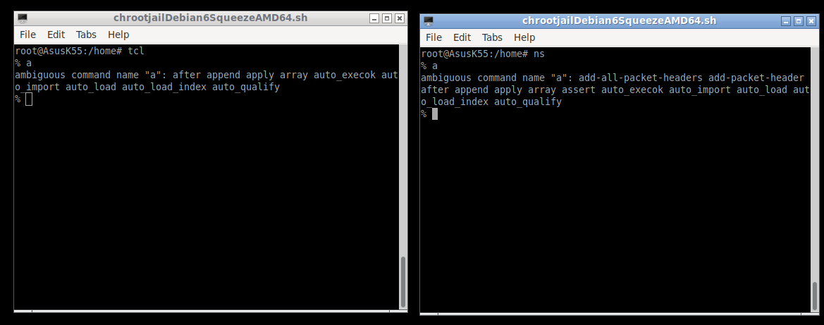
Both the terminals are trying to display the commands starting with “a” – that’s all. But it proves that these two are different versions of tcl.
Ok. Let us run our “welcome” simulation in tcl/ns-2 way.
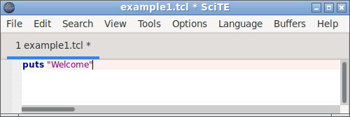
The First Simulation Script example1.tcl:
The following is the only one line of the simulation script ( )
puts "Welcome"
Run ‘example1.tcl’ in both terminals.
Terminal 1:
Terminal 2:
You will just see the “Welcome” message in both of the terminals.
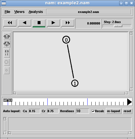
The Second Simulation Script example2.tcl:
Now let us really simulate the simplest ns2 simulation and visualize it with nam.
Of course, this simulation will actually do nothing (but create two ns-2 nodes with a link, and we can visualize them in nam)
The following are the few lines of the simulation script with nam trace output functionality.
example2.tcl
set ns [new Simulator]
set tracefd [open example2.nam w]
$ns namtrace-all $tracefd
set Client [$ns node]
set Server [$ns node]
$ns duplex-link $Client $Server 1.5Mb 10ms DropTail
$ns at 10.0 "$ns flush-trace; $ns halt; exit 0"
$ns run
The following is the nam output of the two-node wired network.
The Third Simulation Script example3.tcl:
Now let us add some traffic in our previous ns2 simulation and visualize it with nam.
The following are the few lines of the simulation script with nam trace output functionality.
example3.tcl
set ns [new Simulator]
set tracefd [open example3.nam w]
$ns namtrace-all $tracefd
set Client [$ns node]
set Server [$ns node]
$ns duplex-link $Client $Server 1.5Mb 10ms DropTail
set src [$ns create-connection TCP $Client TCPSink $Server 1]
set ftp [$src attach-app FTP]
$ns at 0.0 "$ftp start" ;$ns at 9.0 "$ftp stop"
$ns at 10.0 "$ns flush-trace; close $tracefd; $ns halt; exit 0"
The following is the nam output of the two-node wired network with some traffic flows.
A Simple Wireless Example
In the following example, we see a simple wireless network simulation under ns-2.
This simulation is almost similar to most of the examples that you may find on Internet.
But, this is a reduced version of the example simulations.
Generally, the lot of lines that you see on a typical wireless network simulation will give the impression that the simulation script is a tough one. But if we group related lines in a single line (separated with semicolons), then it will become small and more understandable.
Further, if we write the “node-config” line in a different way, then it will avoid a lot of lines that usually “set” different variables at the top of a wireless network simulation script.
Advice: Before trying to understand the following simulation script, please read a good tutorial like[2].
example4.tcl
set ns [new Simulator]
$ns use-newtrace
set eventtracefd [open example4.tr w] ; $ns trace-all $eventtracefd
set namtracefd [open example4.nam w] ; $ns namtrace-all-wireless $namtracefd 500 500
set topo [new Topography] ; $topo load_flatgrid 500 500
create-god 2
set chan_1_ [new Channel/WirelessChannel ]

$ns node-config -adhocRouting AODV -llType LL -macType Mac/802_11 -ifqType Queue/DropTail/PriQueue \
-ifqLen 5 -antType Antenna/OmniAntenna -propType Propagation/TwoRayGround \
-phyType Phy/WirelessPhy -topoInstance $topo \
-movementTrace ON -agentTrace ON -routerTrace ON -macTrace ON -channel $chan_1_ \

set Client [$ns node] ;$Client random-motion 0 ; $Client set X_ 200.0 ; $Client set Y_ 200.0 ; $ns initial_node_pos $Client 20
set Server [$ns node] ;$Server random-motion 0 ; $Server set X_ 300.0 ; $Server set Y_ 300.0 ;$ns initial_node_pos $Server 20
set tcp [new Agent/TCP] ; $ns attach-agent $Client $tcp
set sink [new Agent/TCPSink] ; $ns attach-agent $Server $sink
$ns connect $tcp $sink
set ftp [new Application/FTP] ; $ftp attach-agent $tcp ;$ns at 1.0 "$ftp start"
$ns at 250 "$ns flush-trace; close $eventtracefd ; close $namtracefd"; $ns at 250.01 "$ns halt"
$ns run
 Take Me to Afarion ns-3 iPlayground