Note: This article is nothing but my experimental/learning log. Since it is not related to any serious research or research simulation, no further support will be provided on this area. So, please do not ask any questions through e-mail regarding this article or related to this area – simply you will not get any answers from me.
In our previous article ” Using NODEMCU – ESP8266 Wifi with Arduino IDE for IoT Projects and Experiments.”, I explained the way of programming NODEMCU – ESP8266 Wifi Development Board. This article is nothing but my own learning log of doing the same with ESP8266 – WeMos D1 mini development boards. For detailed information, one may follow the complete articles cited in the reference section, particularly the one from [1] and [2]. Even though the reference[2] deals with NODEMCU – ESP8266 Wifi Development Board, the same can be applicable to ESP8266 – WeMos D1 mini development boards also. This article follows the guidelines from[2] and explains the way of programming ESP8266 – WeMos D1 mini development boards with Arduino IDE for IoT-related Projects and Experiments. We thank the authors of [1] and [2] for providing such a good tutorial on this and giving credit for the WeMos D1 mini images that I used in this article.
ESP8266 – WeMos D1 mini Development Boards[8]
Wemos D1 Mini WIFI Internet Of Things Development Board Based ESP8266, and it is a mini WIFI board based on ESP-8266EX. 11 digital input/output pins, all pins have interrupt/PWM/I2C/one-wire supported(except D0) 1 analogue input(3.3V max input) and a Micro USB connection
The Wemos D1 Mini is a great board to develop WiFi-based IoT Projects. It uses the popular ESP8266 Module for its IoT operations. Can be easily programmed through USB and requires no additional programmer.
Use this tried and tested hardware platform to build your IoT Projects without having to worry about hardware design and fabrication. This board lets you jumpstart your IoT Development by letting you concentrate all your time and effort on software development.
Brief Features and Specification of ESP8266 – WeMos D1 Mini [8]
- 11 digital input/output pins, all pins have interrupt/pwm/I2C/one-wire supported(except D0)
- 1 analog input(3.2V max input)
- Micro USB connection
- Use BRT (Bias Resistor Transistor), easier into flash mode.
- 30% increase in radiating area, more stable.
- Dimensions : 35 x 26 x 8 (LxWxH) mm.
- Weight: 10 gm.
- Board Color : Blue
- Compatible with Arduino
- Compatible with NodeMCU
- Compatible with MicroPython
Note: To know about different versions of WeMos boards, one may follow the reference [9]. Further, there are different clones of these model boards available in the market. So, one should take care of the actual specifications and the pinout of the board that they are using.
Diagram and pinout for version v1.0.0 of WeMos D1 Mini[ 7]


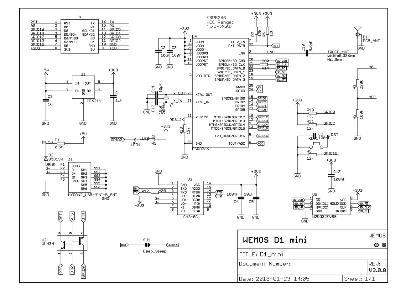
D1 Mini Schematics[7]
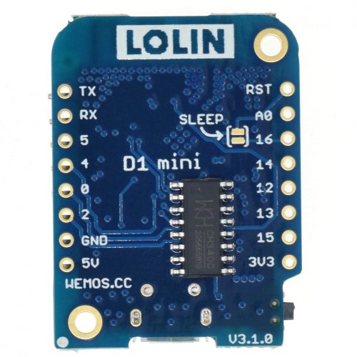
The version 3.1.0 Board

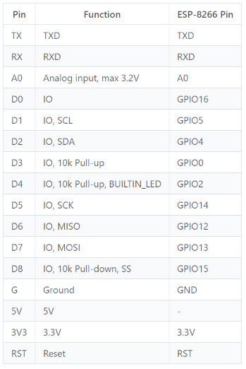
The Pinouts of version 3.1.0 Board
Installing Arduino IDE and necessary components
Step 1: Installing Arduino IDE
First, from[3], install the latest version of Arduino IDE on your computer with respect to the operating system that you are using.
Step 2: Installing necessary components in Arduino IDE
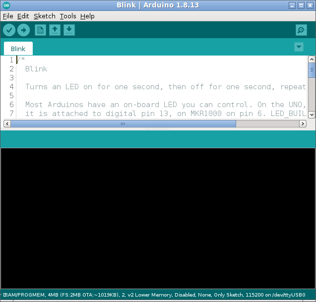
Start the Arduino IDE and you may open the example “Blink”
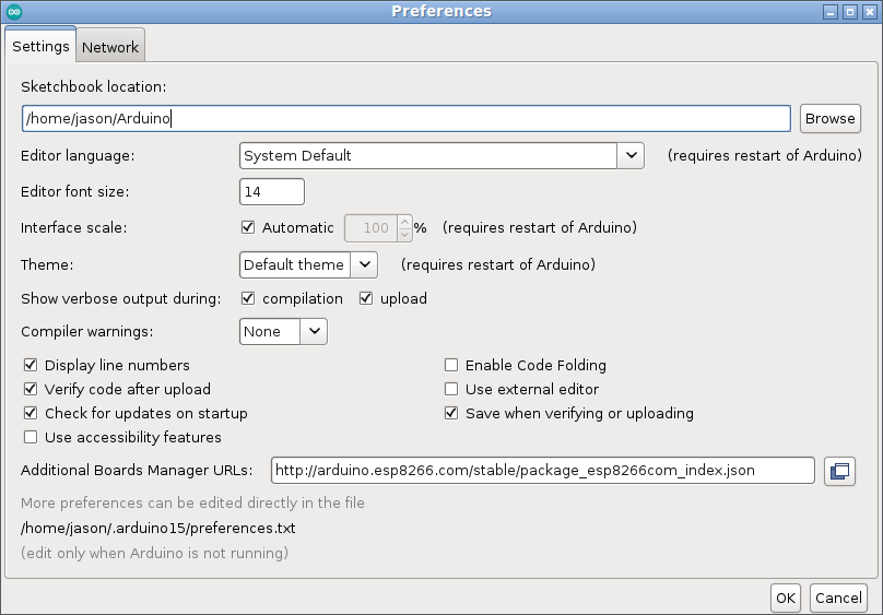
Step 3: Set Additional Board Manager URL
From the menu File -> Preferences, set the set the Additional Board Manager URL as
“http://arduino.esp8266.com/stable/package_esp8266com_index.json”
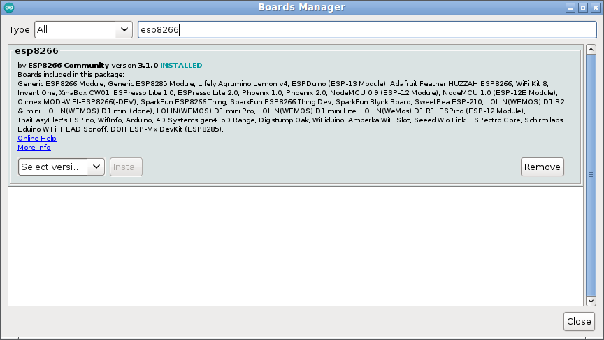
Step 4: Installing the Components needed for ESP8266
From the menu Tools -> Boards -> Board Manager, select ESP8266 by ESP8266 Community and install it.
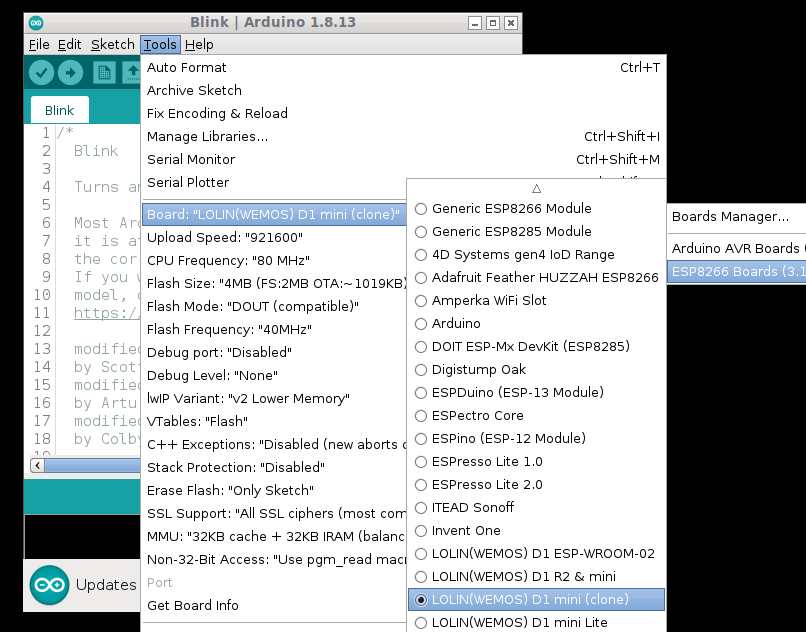
Step 5: Select the NodeMCU board as follows:
Select the LOLIN(WEMOS) D1 mini (clone) or any suitable one as per your need, from the Menu Tools -> Board -> ESP8266 Boards -> “LOLIN(WEMOS) D1 mini (clone)” as follows
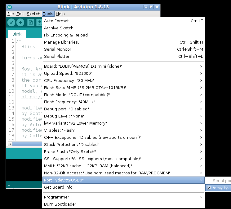
Step 6: Set the Serial Port
Now connect the board to the computer using a suitable micro USB connector cable.
From the menu Tools -> Port, select the appropriate serial port in which the board is connected now.
Step 7: Program the Board
The following is the example program provided along with the Arduino IDE:
/*
Blink
Turns an LED on for one second, then off for one second, repeatedly.
Most Arduinos have an on-board LED you can control. On the UNO, MEGA and ZERO
it is attached to digital pin 13, on MKR1000 on pin 6. LED_BUILTIN is set to
the correct LED pin independent of which board is used.
If you want to know what pin the on-board LED is connected to on your Arduino
model, check the Technical Specs of your board at:
https://www.arduino.cc/en/Main/Products
modified 8 May 2014
by Scott Fitzgerald
modified 2 Sep 2016
by Arturo Guadalupi
modified 8 Sep 2016
by Colby Newman
This example code is in the public domain.
http://www.arduino.cc/en/Tutorial/Blink
*/
// the setup function runs once when you press reset or power the board
void setup() {
// initialize digital pin LED_BUILTIN as an output.
pinMode(LED_BUILTIN, OUTPUT);
}
// the loop function runs over and over again forever
void loop() {
digitalWrite(LED_BUILTIN, HIGH); // turn the LED on (HIGH is the voltage level)
delay(1000); // wait for a second
digitalWrite(LED_BUILTIN, LOW); // turn the LED off by making the voltage LOW
delay(1000); // wait for a second
}
Now you may try programming the board by selecting a simple example sketch such as “Blink”. On successful compiling and uploading, you will end up with a screen like this :
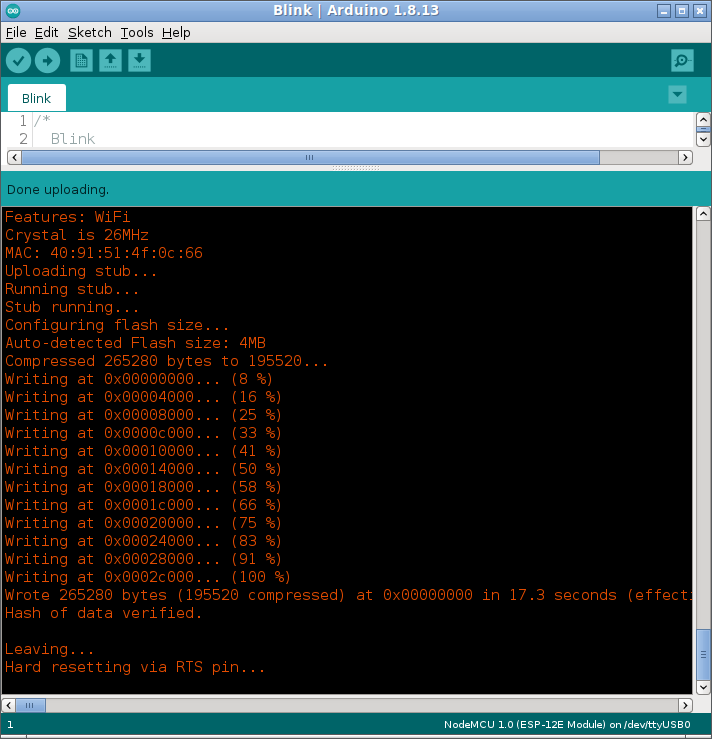
On successful upload of the “Blink” example sketch, now the LED in the board will start to blink as shown in[10].
The Different ESP8266 chips, Development Boards and their capabilities.
Conclusion
ESP8266 – WeMos D1 mini Wifi Development Board is a good board to start with our IoT-related projects and experiments. We may see the way of programming and using the onboard WiFi in another article. It is possible to implement the LoRaWAN project using a suitable, real IoT Development Board
It is possible to do serious research work by making these IoT devices to communicate with a running ns-3 simulation (with some emulated ns-3 nodes). This makes it possible to do sensor network-related research simulations with a lot of emulated and real nodes. In that case, researchers are advised to read the following article :
Sending ICMP Traffic From an ns-3-FdNetDevice Node to a Real Host Over a Real Channel
References
- Pieter P, A Beginner’s Guide to the ESP8266, 08-03-2017
- https://lastminuteengineers.com/esp8266-nodemcu-arduino-tutorial/
- https://www.arduino.cc/en/software
- https://www.mischianti.org/2019/08/20/wemos-d1-mini-esp8266-specs-and-ide-configuration-part-1/
- http://esp8266.net/
- https://www.wemos.cc/en/latest/d1/d1_mini.html
- https://escapequotes.net/esp8266-wemos-d1-mini-pins-and-diagram/
- https://www.electronicscomp.com/
- https://www.wemos.cc/en/latest/index.html
- https://www.iotstarters.com/coding-the-wemos-d1-mini-using-arduino-ide/
 Take Me to Afarion ns-3 iPlayground