Note:
This project is almost a two-decade old. If you are an electronics hobbyist, then you may try this. If you are a graduate or postgraduate student, then please try to do a project on some latest technologies.
No more support will be provided for any of these old student-contributed projects. Even you will not get any reply if you raise any query in this regard – sorry.
Introduction
Security is a primary issue in a modern domestic and office environment. Today, almost every house is equipped with a Personal Computer. In this project, we propose a simple model for domestic security against burglary by implementing a simple
The Sensor Node
The Sensor SystemAssembled Circuit
The above picture shows the Assembled sensor system. The four thin wires (two pairs of twisted wires) shown in the left side of the picture is the main sensor cables which will be connected through the gates/doors of the house. They will be connected in such a way that they will be grounded while the doors/gates will be in the closed state. The right side cable is the RS232 interface. The cable in the top (black) is the power cable which will be connected to the 230V mains supply of the house or any uninterrupted power supply.
The following picture is the close-up view of the same sensor system.
The Main Circuit Board
The Sensor Data is Retrieved And Displayed at PC End
The Following screen output shows the sensor data gathered at PC end. The Baud Rate of PC com post was set to 2400 because the 8051 is communicating at that speed.
Monitoring Data from System
The Sensor Node Interfaced with the PC
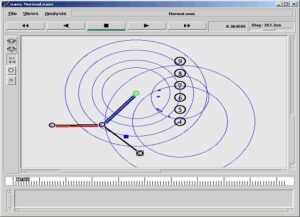
In the following picture the sensor system is interfaced with a pc via serial port. The application specially designed for controlling and monitoring the system is receiving data from the system.
The System Interfaced with a PC
About the Proposed System
The proposed security system has been implemented using the simple 8051 Microcontroller and can function autonomously and independently without the computer. The system can be connected with the PC through serial port and can be controlled and monitored from the PC using the specially designed serial communication software. This security system will be in a domestic environment to provide some simple security solutions like burglar alarms in different doors and windows. The Firm ware of the system will be developed using a suitable compiler meant for 8051. The remaining part of the project is proposed to be implemented using Microsoft Visual C++ under Windows XP.
The Reasons for Selecting 8051 Micro Controller
The 8051 family of micro controller is selected for implementing the proposed sensor system, because it is the most cheapest and commonly available microcontroller in the market. It is based on an architecture which is highly optimized for control systems. It is used in a wide variety of applications from military equipment to automobiles to the keyboard of the PC. The 8051 family of microcontrollers is available in a wide array of variations from manufacturers such as Intel, Philips, and Siemens. These manufacturers have added numerous features and peripherals to the 8051 such as I2C interfaces, analog to digital converters, watchdog timers, and pulse width modulated outputs. Variations of the 8051 with clock speeds up to 40MHz and voltage requirements down to 1.5 volts are available. This wide range of parts based on one core makes the 8051 family an excellent choice as the base architecture for a company’s entire line of products since it can perform many functions and developers will only have to learn this one platform. It has a Full duplex UART, so this micro-controller can be used for constructing the proposed PC vs hardware network.
About the Implementation
The hardware will be assembled on readily available general purpose PCBs and the power for each and every nodes will be provided from a common power source. The Firmware of the 8051 system will be developed by using suitable programming language. The software at the PC side will be developed using VC++ for gathering the sensor data and visualizing the house.
The Architecture of 8051 and Serial Communication
The Intel 8051 was a Harvard architecture single chip microcontroller (µC) developed by Intel in 1980 for use in systems. It was extremely popular in the 1980s and early 1990s, but today it has largely been superseded by a vast range of enhanced devices with 8051-compatible processor cores that are manufactured by more than 20 independent manufacturers including Atmel, Maxim IC (via its Dallas Semiconductor subsidiary), Philips, Winbond, and Silicon Laboratories.
Intel’s original 8051 family was developed using NMOS technology, but later versions, identified by a letter “C” in their name, e.g. 80C51, used CMOS technology and were less power-hungry than their NMOS predecessors – this made them eminently more suitable for battery-powered devices.
Important Features of 8051
It contains Processor (CPU), RAM, ROM, Serial Port , Parallel Port, Interrupt logic, Timer etc.
Data bus – 8 bit data bus. Can access 8 bit data in one operation. Hence called 8-bit microprocessor.
Address bus – 16 bit address bus. Can access 216 memory locations i.e 64 KB of memory each of RAM and ROM.
On chip RAM – 128 Bytes (Data Memory).
On chip ROM – 4 KB (Program Memory).
Four Byte bi-directional Input Output port.
UART (Serial Port).
Two 16 – bit Up-Counter.
Two level interrupt priority.
Power saving mode.
A particularly useful feature of the 8051 core is the inclusion of a boolean processing engine which allows bit-level boolean logic operations to be carried out directly and efficiently on internal registers and RAM. This feature helped to cement the 8051’s popularity in industrial control applications. Another valued feature is that it has four separate register sets, which can be used to greatly reduce interrupt latency compared to the more common method of storing interrupt context on a stack. The 8051 UART can be configured to use a 9th data bit that can provide addressable communications in an RS-485 multi-point communications environment.
8051 based microcontrollers typically include one or two UARTs, two or three timers, 128 or 256 bytes of internal data RAM (16 bytes of which are bit-addressable), up to 128 bytes of I/O, 512 bytes to 128kb of internal program memory, and sometimes a quantity of extended data RAM (ERAM) located in the program address space. The original 8051 core ran at 12 clock cycles per machine cycle, with most instructions executing in one or two machine cycles. With a 12 MHz clock frequency, the 8051 could thus execute 1 million one-cycle instructions per second or 500,000 two-cycle instructions per second. Enhanced 8051 cores are now commonly used which run at six, four, two, or even one clock per machine cycle, and have clock frequencies of up to 100 MHz, and are thus capable of an even greater number of instructions per second.
Conclusion And Further Enhancements
The proposed model of the security system has been successfully designed and implemented. The security system has been successfully interfaced with a desktop computer and the sensor data were retrieved in regular intervals.
Using the serial communication program, the operations of the sensor nodes can be controlled using the Tx Operation. The performance of the system was evaluated with different operating conditions and modes. The system was tested with different speeds of data transfer. The proposed system achieved the performance which will be sufficient for more practical house security systems.
The sensor system was designed in such a way to interface it with more similar sensor systems to function as a huge security network. But in this project, that feature was not tested since we developed only a single sensor system. In future, one may extend this functionality to get sensor data from very large house or office environment.
 Take Me to Afarion ns-3 iPlayground