Discuss Through WhatsApp
From LTE to 5G-NR: Evolution and Fundamentals of 5G Network Simulation in ns-3
Author: Charles Pandian |
Target Simulator: ns-3 (5G-LENA / nr Module) |
3GPP Standards: Release 15 / 16 / 17 |
Domain: 5G-NR, Massive MIMO, Beamforming & Cellular Core
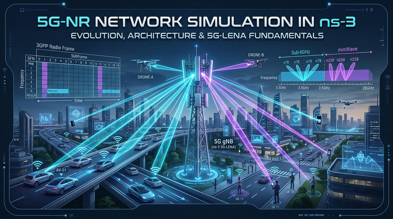
Cellular telecommunication systems are among the most intricate distributed engineering systems ever devised. Unlike local area networks (such as Wi-Fi) where nodes contend for shared unlicensed airwaves using carrier-sense protocols, cellular networks operate in licensed spectrum under centralized base station control with millisecond-scale resource allocation, dynamic channel state tracking, fast hybrid retransmissions, and multi-hop core tunneling.
For academic scholars, PhD candidates, and telecommunication researchers, deploying physical 5G base stations (gNBs) and user terminals (UEs) is cost-prohibitive and geographically constrained. Network simulation with ns-3 provides the gold standard platform for repeatable, standards-compliant, and mathematically rigorous investigation of next-generation cellular protocols.
This guide explores the complete evolutionary journey of mobile cellular network simulation in ns-3—from early ad-hoc models through the landmark 4G LENA project and NYU mmWave modules, culminating in modern 5G-LENA (5G New Radio)—followed by an in-depth exploration of the core architectural fundamentals governing 5G-NR simulation.
Article Navigation Index
1. The Evolutionary History of Mobile Cellular Simulation in ns-3
The simulation of mobile telecommunication systems under ns-3 was not built in a single day. It represents more than two decades of architectural evolution, shifting from ad-hoc experimental patches to industrial-grade 3GPP standards compliance.
A. The Pre-Cellular Era: ns-2 Legacy & Early ns-3 Limitations
In the era of ns-2 (late 1990s through mid-2000s), network research was heavily focused on wired Internet protocols (TCP/IP) and IEEE 802.11 Wi-Fi ad-hoc / MANET networks. Simulating cellular networks (such as 2G GSM/GPRS and 3G UMTS/CDMA) in ns-2 was notoriously difficult:
- Fragmented Patches: Cellular extensions (like EURANE for UMTS/HSDPA) were third-party patches that frequently broke with new compiler versions and were never merged into mainline ns-2.
- Lack of Core Realism: Early models abstracted away base station schedulers, power control, and the cellular core network (SGSN, GGSN), treating mobile towers as generic point-to-point links with statistical delays.
- The Dual-Language Bottleneck: The split-architecture of ns-2 (C++ for packet processing and OTcl for simulation scripting) made complex state machines like Radio Resource Control (RRC) and Hybrid ARQ cumbersome to maintain and debug.
When ns-3 was created in 2008 as a ground-up C++ redesign, early releases (ns-3.1 to ns-3.12) initially lacked native cellular support. The community focused on WiMAX (IEEE 802.16) via the wimax module, which served as an early testing ground for OFDMA frame structures and scheduled downlink/uplink transmissions.
B. The LENA Project: The 4G LTE Milestone in ns-3
The true cellular breakthrough occurred between 2011 and 2013 with the launch of the LENA (LTE-EPC Network Architecture) project. Spearheaded by the Centre Tecnològic de Telecomunicacions de Catalunya (CTTC) in Barcelona and supported by industrial sponsors, LENA was designed to produce an open-source, carrier-grade LTE and EPC simulator fully integrated into ns-3.
Merged into ns-3 mainline in release ns-3.13, the lte module introduced two revolutionary pillars:
-
The E-UTRAN Radio Protocol Stack:
Accurately modeled the complete protocol stack of the eNodeB and User Equipment (UE):- LTE PHY: OFDMA downlink and SC-FDMA uplink, detailed SINR calculation via spectrum models, CQI generation, and MCS (Modulation and Coding Scheme) mapping.
- LTE MAC: Realistic multi-user schedulers operating on 1 ms Subframe Transmission Time Intervals (TTIs), including Proportional Fair (PF), Round Robin (RR), Maximum Throughput, and Throughput-to-Average.
- RLC & PDCP: Complete Radio Link Control (Transparent, Unacknowledged, and Acknowledged modes) and Packet Data Convergence Protocol with buffer status reporting.
- RRC & Handover: 3GPP RRC protocol state machines with automatic handover algorithms based on measurement reports (A2-A4, Event A3).
-
The Evolved Packet Core (EPC):
Unlike previous cellular tools that simulated isolated radio links, LENA provided a functional core network architecture:- Simulated the Serving Gateway (SGW), Packet Data Network Gateway (PGW), and Mobility Management Entity (MME).
- Implemented realistic GTP-U (GPRS Tunneling Protocol User Plane) encapsulation over UDP/IP on the S1-U interface.
- Seamlessly bridged real ns-3 TCP/IP sockets from remote Internet hosts through the EPC directly to mobile UEs.
The LENA project transformed ns-3 into the dominant academic and industrial simulator for LTE, LTE-Advanced, Carrier Aggregation, and Licensed-Assisted Access (LAA/LTE-U).
C. The mmWave Research Bridge: Paving the Path to 5G
Around 2015, telecommunication research shifted toward millimeter-wave (mmWave) frequencies (28 GHz, 38 GHz, and 73 GHz) to deliver multi-gigabit throughput. Because the standard LTE module was hardcoded to sub-3 GHz microwave channel properties, a collaborative research team from NYU WIRELESS (led by Prof. Theodore Rappaport) and the University of Padova (led by Prof. Michele Zorzi) developed the ns3-mmwave module.
The mmWave module bridged the critical gap between 4G and 5G by introducing:
- 3D Spatial Statistical Channel Models: Implementing early 3GPP TR 38.900 channel models with spatial consistency, clustered multi-path components, and atmospheric attenuation.
- Directional Beamforming & Phased Arrays: Modeling antenna arrays that focus narrow high-gain beams to overcome severe path loss at high frequencies.
- Customized TDD Slot Framing: Sub-millisecond slot structures and flexible directional control channels.
D. The 5G-LENA Milestone: 3GPP 5G New Radio (NR) in ns-3
Recognizing the need for a unified, standards-compliant 5G simulation platform adhering to 3GPP Release 15, 16, and 17 specifications, CTTC developed 5G-LENA (the nr module), incorporating the lessons of both LTE-LENA and mmWave.
5G-LENA redesigned the PHY and MAC foundations from scratch to support flexible subcarrier numerologies ($mu = 0$ to $4$), Bandwidth Parts (BWP), variable-symbol slot allocations, mini-slots for Ultra-Reliable Low-Latency Communication (URLLC), massive MIMO beamforming, and dual-connectivity configurations (Option 3x Non-Standalone and Option 2 Standalone).
2. Fundamentals of 5G Network Simulation in ns-3
Simulating a 5G-NR cellular network in ns-3 requires an understanding of how 3GPP physical, radio link, and core network specifications are abstracted into C++ software classes.
A. The 5G-NR Radio Protocol Stack Architecture
In ns-3 (specifically within 5G-LENA), the 5G radio interface is divided into a layered hierarchy mirroring real 3GPP User Plane protocols:
| Layer | 3GPP Protocol Name | ns-3 Implementation Class | Key Simulation Responsibilities |
|---|---|---|---|
| SDAP | Service Data Adaptation Protocol | ns3::NrSdapEntity |
Maps IP packets to 5G QoS Flows based on 5QI (5G QoS Identifiers) and assigns them to Data Radio Bearers (DRBs). |
| PDCP | Packet Data Convergence Protocol | ns3::LtePdcp / NrPdcp |
Maintains sequence numbering, handles in-order packet delivery, duplicate detection, and header compression abstractions. |
| RLC | Radio Link Control | ns3::LteRlcUm / LteRlcAm |
Segments and reassembles packets to fit MAC transport block sizes. Operates in UM (Unacknowledged) or AM (Acknowledged with ARQ). |
| MAC | Medium Access Control | ns3::NrGnbMac / NrUeMac |
Multi-user OFDMA dynamic scheduling, Bandwidth Part (BWP) allocation, and Stop-and-Wait Hybrid ARQ (HARQ) management. |
| PHY | Physical Layer | ns3::NrGnbPhy / NrUePhy |
Flexible numerology slot timing, SINR computation, LDPC coding curves, beamforming gain evaluation, and spectrum transmission. |
B. 5G Physical Layer: Flexible Numerology & Slot Durations
In legacy 4G LTE, subcarrier spacing was rigidly fixed at 15 kHz, and each subframe was locked to a 1.0 ms duration containing exactly 14 OFDM symbols. 5G New Radio replaces this with flexible numerology ($mu$):
Slot Duration = 1 / 2μ ms
This allows ns-3 simulations to adapt the radio interface to radically different performance goals:
| Numerology (μ) | Subcarrier Spacing | Slot Duration | Slots per 10 ms Frame | Typical Spectrum & Use Case |
|---|---|---|---|---|
| μ = 0 | 15 kHz | 1.0 ms | 10 slots | FR1 (Sub-1 GHz / Sub-3 GHz) Wide-area coverage (eMBB) |
| μ = 1 | 30 kHz | 0.5 ms | 20 slots | FR1 (C-Band / 3.5 GHz n78). Most common commercial 5G. |
| μ = 2 | 60 kHz | 0.25 ms | 40 slots | FR1 & Lower FR2 mmWave. Low-latency URLLC. |
| μ = 3 | 120 kHz | 0.125 ms (125 μs) | 80 slots | FR2 mmWave (28 GHz / 39 GHz). Ultra-high data rates. |
| μ = 4 | 240 kHz | 0.0625 ms (62.5 μs) | 160 slots | High-frequency synchronization and ultra-low latency signaling. |
C. 3GPP TR 38.901 3D Spatial Channel Models
Accurate 5G simulation demands physical propagation models capable of evaluating multi-path fading across both sub-6 GHz and millimeter-wave frequencies. ns-3 natively provides the 3GPP TR 38.901 channel modeling suite via the ThreeGppPropagationLossModel and ThreeGppSpectrumPropagationLossModel classes.
These models evaluate:
- Standard 3GPP Deployment Scenarios: Urban Macro (
ThreeGppUmaPropagationLossModel), Urban Micro (ThreeGppUmiStreetCanyonPropagationLossModel), Rural Macro (ThreeGppRmaPropagationLossModel), and Indoor Hotspot (ThreeGppIndoorOfficePropagationLossModel). - Stochastic LOS / NLOS Probabilities: Computes the probability that a mobile UE has Line-of-Sight or Non-Line-of-Sight visibility based on distance and 3D building geometry.
- Spatial Consistency: Ensures that when a node moves a few centimeters, its channel multi-path parameters vary smoothly rather than jumping discontinuously.
D. Phased Arrays & Massive MIMO Beamforming
Because high-frequency signals attenuate rapidly over distance, 5G gNBs utilize massive antenna arrays (e.g., 8×8 or 16×16 elements) to direct energy toward specific users. In ns-3:
- Antennas are modeled using the
UniformPlanarArrayclass, defining the number of rows, columns, polarization, and antenna element spacing. - Beamforming algorithms calculate complex weight vectors. Common algorithms include:
- DirectPathBeamforming: Points the antenna beam’s main lobe directly at the line-of-sight vector between gNB and UE.
- QuasiOmniBeamforming: Emits an omnidirectional-like pattern for initial cell discovery and synchronization signals.
- CellScanBeamforming: Emulates exhaustive beam sweep patterns across angular sectors.
E. Bandwidth Parts (BWP) & OFDMA Scheduling
In 5G-NR, a carrier bandwidth can span up to 100 MHz (FR1) or 400 MHz (FR2). Because mobile phones cannot monitor a 400 MHz channel continuously without draining battery life, 5G introduces Bandwidth Parts (BWP):
- A BWP is a contiguous subset of Physical Resource Blocks (PRBs) configured with a specific numerology ($mu$).
- In 5G-LENA, the
NrGnbMacschedules resources per-BWP using OFDMA schedulers:NrMacSchedulerOfdmaPF: Proportional Fair scheduler balancing spectral efficiency and fairness.NrMacSchedulerOfdmaRR: Round Robin scheduler distributing slots equally.NrMacSchedulerOfdmaMR: Maximum Rate scheduler prioritizing UEs with the highest instantaneous SINR.
F. Core Network Architectures: EPC vs 5G Core (5GC)
ns-3 models two distinct 3GPP architectural deployment options:
- Non-Standalone (NSA – Option 3x): 5G gNB radio stations handle high-speed user plane data, but the control plane is anchored to an existing 4G LTE EPC (MME/SGW/PGW). This is the default in many 5G-LENA research scripts due to its computational efficiency.
- Standalone (SA – Option 2): Pure 5G end-to-end architecture where gNBs connect directly to 5G Core (5GC) Network Functions: the AMF (Access and Mobility Management Function), SMF (Session Management Function), and UPF (User Plane Function).
3. Practical 5G-NR Simulation Blueprint in C++
The following script demonstrates the structural anatomy of a modern 5G simulation script using the 5G-LENA nr architecture. It configures a 28 GHz mmWave carrier with numerology $mu = 3$, attaches directional beamforming antenna arrays, creates a 3GPP UMi channel model, and streams high-throughput traffic through the core network to a mobile terminal:
/*
 * 5G-NR Simulation Blueprint in ns-3 (5G-LENA Architecture)
 * Author: Charles Pandian | ProjectGuideline.com
 */
#include "ns3/core-module.h"
#include "ns3/network-module.h"
#include "ns3/mobility-module.h"
#include "ns3/internet-module.h"
#include "ns3/applications-module.h"
#include "ns3/point-to-point-module.h"
#include "ns3/nr-module.h"

using namespace ns3;

NS_LOG_COMPONENT_DEFINE("5gNetworkSimulationBlueprint");

int main(int argc, char *argv[])
{
    // =========================================================================
    // 1. Simulation Parameters
    // =========================================================================
    uint16_t numGnb = 1;
    uint16_t numUe = 2;
    double simTime = 5.0; // seconds
    double centralFrequency = 28e9; // 28 GHz mmWave (FR2)
    double bandwidth = 100e6;        // 100 MHz channel bandwidth
    uint16_t numerology = 3;         // mu = 3 (120 kHz subcarrier spacing)
    double gnbTxPower = 30.0;        // 30 dBm transmit power

    CommandLine cmd(__FILE__);
    cmd.AddValue("simTime", "Simulation time in seconds", simTime);
    cmd.AddValue("centralFrequency", "Carrier central frequency in Hz", centralFrequency);
    cmd.AddValue("bandwidth", "System bandwidth in Hz", bandwidth);
    cmd.AddValue("numerology", "5G-NR Numerology (0 to 4)", numerology);
    cmd.Parse(argc, argv);

    // =========================================================================
    // 2. Node Creation & Topology Containers
    // =========================================================================
    NodeContainer gnbNodes;
    NodeContainer ueNodes;
    gnbNodes.Create(numGnb);
    ueNodes.Create(numUe);

    // Grid / Position Allocation
    MobilityHelper mobility;
    mobility.SetMobilityModel("ns3::ConstantPositionMobilityModel");

    Ptr posAlloc = CreateObject();
    posAlloc->Add(Vector(0.0, 0.0, 10.0));   // gNB at 10m elevation
    posAlloc->Add(Vector(50.0, 0.0, 1.5));   // UE 0 at 50m distance
    posAlloc->Add(Vector(100.0, 0.0, 1.5));  // UE 1 at 100m distance
    mobility.SetPositionAllocator(posAlloc);
    mobility.Install(gnbNodes);
    mobility.Install(ueNodes);

    // =========================================================================
    // 3. 5G-NR Helper & Core Network Setup
    // =========================================================================
    Ptr epcHelper = CreateObject();
    Ptr idealBeamformingHelper = CreateObject();
    Ptr nrHelper = CreateObject();

    nrHelper->SetBeamformingHelper(idealBeamformingHelper);
    nrHelper->SetEpcHelper(epcHelper);

    // Configure 3GPP TR 38.901 Urban Micro (UMi) Channel Model
    nrHelper->SetChannelConditionModelAttribute("Type", TypeIdValue(ThreeGppUmiStreetCanyonChannelConditionModel::GetTypeId()));
    nrHelper->SetPathlossAttribute("Type", TypeIdValue(ThreeGppUmiStreetCanyonPropagationLossModel::GetTypeId()));

    // =========================================================================
    // 4. Bandwidth Part (BWP) & Physical Layer Configuration
    // =========================================================================
    CcBwpCreator ccBwpCreator;
    const uint8_t numCc = 1;
    CcBwpCreator::SimpleOperationBandConf bandConf(centralFrequency, bandwidth, numCc, BandwidthPartInfo::UMi_StreetCanyon);
    OperationBandInfo band = ccBwpCreator.CreateOperationBandContiguousCc(bandConf);

    nrHelper->InitializeOperationBand(&band);

    // Set gNB transmission attributes
    nrHelper->SetGnbPhyAttribute("TxPower", DoubleValue(gnbTxPower));
    nrHelper->SetGnbPhyAttribute("Numerology", UintegerValue(numerology));

    // Install 5G NetDevices on gNodeB and UEs
    NetDeviceContainer gnbNetDev = nrHelper->InstallGnbDevice(gnbNodes, band);
    NetDeviceContainer ueNetDev = nrHelper->InstallUeDevice(ueNodes, band);

    // =========================================================================
    // 5. Internet Stack & Routing via Core Network
    // =========================================================================
    InternetStackHelper internet;
    internet.Install(ueNodes);

    // Assign IP addresses to UEs through the EPC helper
    Ipv4InterfaceContainer ueIpIface = epcHelper->AssignUeIpv4Address(NetDeviceContainer(ueNetDev));

    // Attach UEs to the gNB (initiates RRC connection)
    nrHelper->AttachToClosestGnb(ueNetDev, gnbNetDev);

    // =========================================================================
    // 6. Application Workload (UDP CBR Traffic Flow)
    // =========================================================================
    uint16_t port = 1234;
    PacketSinkHelper sinkHelper("ns3::UdpSocketFactory", InetSocketAddress(Ipv4Address::GetAny(), port));
    ApplicationContainer sinkApps = sinkHelper.Install(ueNodes.Get(0));
    sinkApps.Start(Seconds(0.5));
    sinkApps.Stop(Seconds(simTime));

    // Traffic generator from Remote Core Host to UE
    OnOffHelper onoff("ns3::UdpSocketFactory", InetSocketAddress(ueIpIface.GetAddress(0), port));
    onoff.SetAttribute("DataRate", StringValue("50Mbps"));
    onoff.SetAttribute("PacketSize", UintegerValue(1400));
    ApplicationContainer clientApps = onoff.Install(epcHelper->GetPgwNode());
    clientApps.Start(Seconds(1.0));
    clientApps.Stop(Seconds(simTime));

    // =========================================================================
    // 7. Data Collection & Simulation Teardown
    // =========================================================================
    nrHelper->EnableTraces(); // Generates NrGnbPhyRxTrace, NrUePhyRxTrace, etc.

    Simulator::Stop(Seconds(simTime));
    Simulator::Run();
    Simulator::Destroy();
    return 0;
}
4. Cellular Generations in ns-3: Architectural Comparison Matrix
Understanding the progression of mobile network simulation in ns-3 across generations is essential for selecting the appropriate module for your research:
| Feature / Dimension | 4G LTE (lte / LENA) |
Early mmWave (ns3-mmwave) |
5G-NR (nr / 5G-LENA) |
|---|---|---|---|
| 3GPP Standard | Release 8 to 10 | Pre-5G Experimental | Release 15, 16, and 17 |
| Operating Frequency | Sub-3 GHz (Microwave) | 28 GHz & 73 GHz (mmWave only) | FR1 (Sub-6 GHz) & FR2 (mmWave) |
| Subcarrier Spacing | Fixed 15 kHz | Fixed per experiment | Flexible Numerology μ ∈ {0,1,2,3,4} |
| Slot Duration | Fixed 1.0 ms (Subframe) | Variable sub-millisecond | 1.0 ms down to 62.5 μs + Mini-slots |
| Channel Model | Rayleigh / Jakes empirical | 3GPP TR 38.900 Statistical | 3GPP TR 38.901 3D Spatial (UMa, UMi, RMa, InH) |
| Antennas / MIMO | SISO & basic 2×2 / 4×4 MIMO | Directional phased arrays | Massive MIMO, Uniform Planar Arrays, 3D Beamforming |
| Spectrum Slicing | None (Monolithic carrier) | Component Carriers | Bandwidth Parts (BWP) Adaptation |
| Core Network | 4G EPC (SGW, PGW, MME) | Anchored to LTE EPC | Option 3x (EPC NSA) & Option 2 (5GC SA) |
About the Author
Charles Pandian is the founder and lead research contributor at ProjectGuideline.com, specializing in ns-2 and ns-3 network simulations, 3D cellular and non-terrestrial satellite networks, and next-generation protocol modeling. For further simulation scripts, custom protocol modules, and research consulting, explore the dedicated ns-3 simulation repository.
 Take Me to Afarion ns-3 iPlayground