Discuss Through WhatsApp
802.11be & 802.11bn
An in-depth architectural analysis of IEEE 802.11be (Wi-Fi 7 / Extremely High Throughput) and the emerging IEEE 802.11bn (Wi-Fi 8 / Ultra High Reliability) standards. This article explores Multi-Link Operation (MLO) across 2.4 GHz, 5 GHz, and 6 GHz bands, Enhanced Channel Sounding and Multi-AP Coordination (CoBF, CoSR, Co-OFDMA), and deterministic Restricted TWT scheduling engineered for dense AR/VR enterprise deployments.
1. The Evolutionary Arc: From Peak Throughput to Ultra-High Reliability
For more than two decades, each successive generation of the IEEE 802.11 standard has pursued a singular headline metric: raw peak PHY throughput. From the 54 Mbps of 802.11a/g to the 6.9 Gbps of 802.11ac (Wi-Fi 5) and the spectral efficiency enhancements of 802.11ax (Wi-Fi 6/6E), improvements were achieved primarily through wider channels, higher-order modulations, and denser spatial multiplexing.
However, modern networking applications—specifically Cloud Extended Reality (AR/VR/XR), untethered surgical robotics, multi-user 8K telepresence, and industrial automation—do not fail due to insufficient average bandwidth. They fail due to tail latency spikes, packet delay variation (jitter), and unpredictability under dense radio contention.
This reality has triggered a major paradigm shift spanning two complementary standardizations:
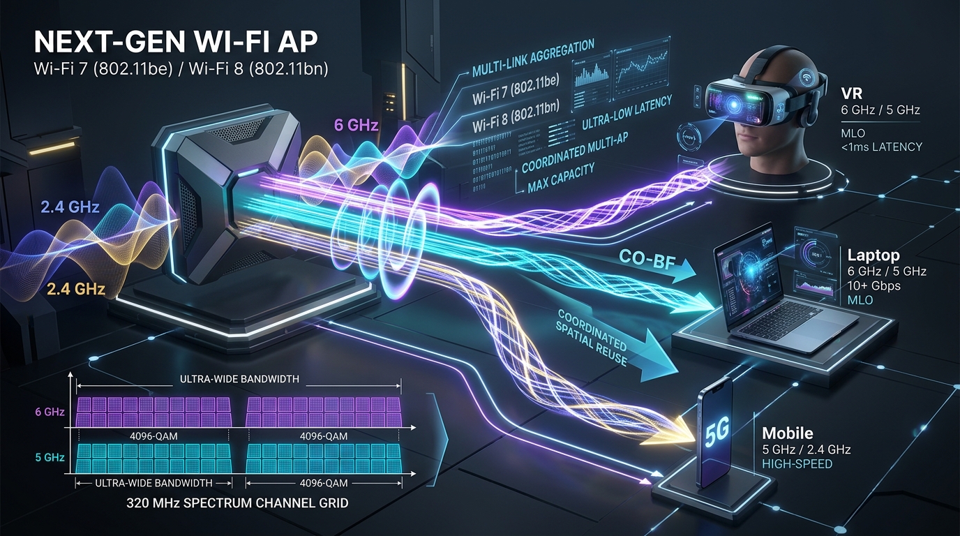
- IEEE 802.11be (Wi-Fi 7 – Extremely High Throughput, EHT): While supporting monstrous theoretical PHY rates up to 46.1 Gbps via 320 MHz channelization, 4096-QAM modulation, and 16×16 MU-MIMO, its true breakthrough lies in Multi-Link Operation (MLO), multi-RU preamble puncturing, and Restricted Target Wake Time (rTWT).
- IEEE 802.11bn (Wi-Fi 8 – Ultra High Reliability, UHR): Shifting the optimization objective entirely away from nominal gigabit headline metrics toward guaranteed worst-case latency bounds (99.999% reliability with < 5 ms latency), seamless AP coordination, deterministic power efficiency, and intelligent peer-to-peer spatial awareness.
2. Multi-Link Operation (MLO): Evaluating Throughput and Latency Benefits
Historically, a Wi-Fi client station (STA) could associate with only a single radio band at any given time (e.g., connecting strictly to 5 GHz or 2.4 GHz). If an associated band experienced sudden congestion, interference, or multi-path fading, the client suffered catastrophic throughput collapse and prolonged backoff delays until executing a sluggish BSS Transition Management (BTM) roaming sequence.
Multi-Link Operation (MLO) represents the most transformative architectural innovation in Wi-Fi 7. It creates an abstraction called the Multi-Link Device (MLD):
The MLD Protocol Architecture
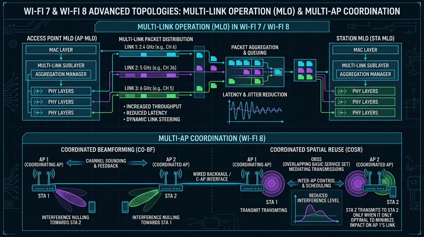
An MLD splits the traditional 802.11 Medium Access Control (MAC) into two distinct sublayers:
1. Upper MAC (UMAC): A centralized, unified sublayer that manages security associations, IP address binding, packet sequence numbering, and end-to-end flow control. To the operating system network stack, the MLD presents a single virtual MAC interface.
2. Lower MAC (LMAC) & PHY: Multiple independent physical instances running simultaneously, each handling channel access (CSMA/CA, EDCA backoff), preamble detection, and physical transmission across distinct frequency links (e.g., Link 1 on 2.4 GHz, Link 2 on 5 GHz, Link 3 on 6 GHz).
2.1 MLO Operating Modes Dissected
The standard defines three foundational operational modes for MLD communication, governed by transceiver hardware capabilities and In-Device Coexistence (IDC) isolation:
- Simultaneous Transmit and Receive (STR) Mode:
The apex of MLO performance. An STR MLD can transmit frames on one link (e.g., Link 2 on 5 GHz) while concurrently receiving frames on another link (e.g., Link 3 on 6 GHz) without self-interference. This requires significant RF physical isolation (typically ≥ 40–50 dB between bands) and steep RF filtering. STR allows completely asynchronous, non-blocking channel access across multiple spectrum bands simultaneously. - Non-Simultaneous Transmit and Receive (NSTR) Mode:
Applicable to cost-sensitive devices or frequency pairs located closely in the spectrum (e.g., 5.8 GHz UNII-3 and 5.925 GHz UNII-5 band edge in 6 GHz). In NSTR, high-power transmission on one link bleeds leakage energy into the adjacent receiver front-end, blinding it. Consequently, if Link 1 starts transmitting, Link 2 cannot simultaneously receive. NSTR links must coordinate their transmission opportunities (TXOPs) using synchronized starting times or aligned packet durations. - Enhanced Multi-Link Single Radio (eMLSR) Mode:
An ingenious low-cost design for consumer smartphones and IoT sensors. The device houses only one active baseband/RF processing chain but possesses multiple antenna frontends that listen simultaneously on 2.4 GHz, 5 GHz, and 6 GHz. As soon as an AP sends an initial control frame (such as an MU-RTS) that wins contention on any link, the client dynamically switches its full radio resources to that winning link within a few microseconds to receive the high-speed data payload.
2.2 Quantifying the Throughput Benefits: Packet Striping and Aggregation
Under MLO Aggregation / Striping Mode, large data frames from a single upper-layer TCP flow are split by the UMAC and dispatched across all available radio links concurrently. Consider a real-world multi-band configuration:
Link 2 (5.0 GHz, 160 MHz, 2×2, 4096-QAM): Peak PHY Rate = 2,882 Mbps
Link 3 (6.0 GHz, 320 MHz, 2×2, 4096-QAM): Peak PHY Rate = 5,764 Mbps
———————————————————————————
Theoretical Aggregated MLO Capacity: ≈ 9,220 Mbps (9.22 Gbps)
In classical single-band operation, an associated client could only achieve a maximum of 5.76 Gbps (if attached to 6 GHz) or 2.88 Gbps (if attached to 5 GHz). MLO yields an immediate 1.6× to 3.2× throughput multiplier by harvesting the aggregate spectral width of all unlicensed bands.
2.3 Quantifying the Latency Revolution: Bypassing Contention Backoffs
While throughput gains are impressive, MLO’s impact on latency and jitter reduction is profound. In traditional single-link CSMA/CA, when a client generates a packet, it must execute clear channel assessment (CCA). If the channel is occupied by an ongoing transmission, the client enters exponential backoff:
In dense networks, repeated collisions double the contention window ($CW$), generating massive tail latency spikes exceeding 80–150 milliseconds. Under MLO Link Switching / Opportunistic Routing:
- The client maintains active backoff counters on all three links simultaneously.
- The moment a latency-critical packet arrives in the UMAC queue, it is immediately dispatched across whichever link finishes its backoff countdown first.
- The probability that all three links are concurrently blocked drops exponentially:
P_{text{all_busy}} = P_{text{busy}}(2.4text{ GHz}) times P_{text{busy}}(5text{ GHz}) times P_{text{busy}}(6text{ GHz})
If each individual band has a 40% channel occupancy probability ($P = 0.4$), the joint probability of all bands being simultaneously congested is merely $0.4^3 = 0.064$ (6.4%).
- Empirical Results: MLO compresses 99.9th percentile worst-case latency from > 100 ms down to under 3.5 ms, completely eliminating head-of-line queuing delays.
For ultra-reliable industrial control or VR head-tracking packets, MLO provides a dedicated Duplication Mode. The UMAC creates two exact replicas of the packet with identical sequence numbers and transmits them concurrently across Link 2 (5 GHz) and Link 3 (6 GHz). Whichever packet arrives first at the receiver is passed up the stack; the redundant duplicate is silently discarded at the LMAC layer. This delivers spatial-frequency diversity gain, slashing packet loss rates from $10^{-2}$ to below $10^{-5}$ without retransmission delays.
3. Architectural Blueprint: MLO and Multi-AP Coordination
To visualize the end-to-end integration of Multi-Link Operation and Multi-AP Coordination, consider the physical and protocol architecture detailed below:
4. Enhanced Channel Sounding & Coordination: The Leap to Wi-Fi 8
In high-density deployments (such as enterprise offices, university lecture halls, and stadium concourses), individual Access Points are deployed within close physical proximity. In legacy Wi-Fi, neighboring APs operate as uncoordinated, competing entities: an AP in BSS A treats transmissions from BSS B as interference, backing off and stalling client traffic.
IEEE 802.11be initiated, and IEEE 802.11bn (Wi-Fi 8) formalizes, Multi-AP Coordination (MAPC)—transforming Wi-Fi from uncoordinated contention into synchronized, cellular-like cooperative radio networks.
4.1 Multi-AP Coordination Mechanisms
1. Coordinated Beamforming (Co-BF)
When two neighboring APs (AP 1 and AP 2) transmit simultaneously on the same channel, AP 1 computes its multi-antenna precoding matrix to steer a spatial null directly toward STA 2 (served by AP 2). Reciprocally, AP 2 steers a spatial null toward STA 1. Both downlink transmissions occur simultaneously at full power with zero co-channel interference.
2. Coordinated OFDMA (Co-OFDMA)
Instead of competing for the entire 80 MHz or 160 MHz channel width, a Coordinating AP negotiates with Coordinated APs over a low-latency wired backhaul or wireless link. The channel is dynamically partitioned into orthogonal Resource Units (RUs): AP 1 transmits to its clients on RUs 1–4, while AP 2 transmits on RUs 5–8 simultaneously.
3. Coordinated Spatial Reuse (CoSR)
Extending Wi-Fi 6 BSS Color, CoSR dynamically adjusts the transmit power of a secondary sharing AP based on pathloss feedback. The secondary AP can transmit concurrently during the primary AP’s TXOP without dropping the primary client’s Signal-to-Interference-plus-Noise Ratio (SINR) below its required MCS decoding threshold.
4. Joint Transmission (J-Tx / Distributed MIMO)
The ultimate frontier in 802.11bn. Multiple physically separated APs share client payload data and transmit synchronized, phase-aligned multi-antenna streams to a single client station, acting as a massive distributed virtual antenna array.
4.2 Enhanced Channel Sounding & Overhead Reduction
Coordinated beamforming and 16×16 MU-MIMO demand precise Channel State Information (CSI) at the transmitter. In classical 802.11, the AP initiates sounding by broadcasting a Null Data Packet Announcement (NDPA) followed by a Null Data Packet (NDP). Every client estimates the channel matrix $mathbf{H}$ and returns a Compressed Beamforming Report (CBR).
However, as channels widen to 320 MHz and antenna counts scale to 16, raw CSI feedback frames explode in size—exceeding dozens of kilobytes per client. Sounding overhead can consume more than 35% of total airtime, erasing throughput gains.
To overcome this, 802.11be and 802.11bn introduce critical sounding enhancements:
- Subcarrier Grouping & Quantization: Grouping 4 or 16 subcarriers with correlated coherence bandwidth into single feedback angles ($psi, phi$).
- Differential & Predictive CSI: Rather than reporting the entire matrix on every sounding cycle, clients report high-frequency differential delta matrices ($Delta mathbf{H}$) relative to a baseline report.
- Multi-AP Sounding Sequences: A single master NDPA coordinates sounding for multiple neighboring APs sequentially, eliminating duplicate feedback overhead across overlapping BSSs.
4.3 Flexible Multiple Resource Units (MRU) & Preamble Puncturing
In 802.11ax (Wi-Fi 6), a client could only be assigned a single contiguous Resource Unit (e.g., one 242-tone RU or one 484-tone RU). Furthermore, if a legacy or radar signal occupied even a 20 MHz slice of an 80 MHz channel, the AP was forced to drop its entire bandwidth back to 40 MHz.
Wi-Fi 7 revolutionizes spectral efficiency through two mechanisms:
- Multiple Resource Units (MRU): Allows non-contiguous subcarrier allocations to a single user (e.g., combining a 242-tone RU with a 484-tone RU). This enables optimal packing of available spectrum around interfering channels.
- Preamble Puncturing: In ultra-wide 320 MHz channels, if a 20 MHz sub-band is occupied by a legacy device or DFS weather radar, the AP simply punctures (notches out) that specific 20 MHz channel while broadcasting across the remaining 300 MHz contiguous and non-contiguous spectrum without discarding the channel.
5. Low-Latency Wi-Fi in Dense Deployments: The AR/VR Imperative
Extended Reality (XR)—encompassing Virtual Reality (VR) and Augmented Reality (AR)—presents the most punishing QoS requirement in commercial wireless history:
The “Motion-to-Photon” (M2P) Constraint
When a user turns their head in a VR headset, the motion sensors register the orientation, send the pose vector to an edge rendering server, the server renders the twin 4K/8K eye buffers, encodes the video stream, and transmits it wirelessly back to the display. The total end-to-end delay must remain strictly below 15–20 milliseconds. Exceeding this boundary induces severe vestibular mismatch, resulting in motion sickness and cognitive disorientation. The wireless link portion of this budget is restricted to ≤ 5 milliseconds at a 99.99th percentile reliability threshold.
5.1 Contention Window Adaptation in Dense Networks
In a multi-user VR arcade or enterprise training facility with 30+ simultaneous headsets, classical 802.11e Enhanced Distributed Channel Access (EDCA) collapses under collision storms. Under standard EDCA:
- High-priority Access Categories (AC_VO and AC_VI) utilize aggressive contention window parameters ($CW_{min} = 3$ or $7$).
- When dozens of stations contend simultaneously with small $CW_{min}$, multiple devices inevitably select the exact same random backoff slot, leading to simultaneous transmission collisions.
- Repeated collisions trigger exponential backoff ($CW_{max} = 15$ or $31$), producing wild latency variance (jitter).
Adaptive Contention Window Tuning: Next-generation firmware implements dynamic EDCA adaptation based on real-time channel feedback:
$$text{CW}_{text{adapted}} = f(text{Collision_Rate}, N_{text{active_XR_stations}})$$
When active station density rises, $CW_{min}$ is dynamically scaled upward just enough to decorrelate transmission slots, preventing the collision avalanche while preserving bounded queueing delay.
5.2 Restricted Target Wake Time (rTWT) Scheduling
While dynamic contention window tuning optimizes contention, Restricted Target Wake Time (rTWT) in 802.11be eliminates contention entirely.
Originally introduced in 802.11ax for IoT battery conservation, TWT allowed stations to negotiate wake periods. In 802.11be, rTWT elevates this into a deterministic quality-of-service reservation engine:
- Deterministic Service Period (SP) Reservation: The AP negotiates periodic, recurring Service Periods exclusively dedicated to latency-critical XR traffic (e.g., an 8 ms SP repeating every 11.1 ms, perfectly aligned with a 90 Hz VR video refresh cycle).
- Non-rTWT Member Silencing: Outside the rTWT group, the AP broadcasts scheduling elements that force all background best-effort devices (laptops downloading updates, background mobile traffic) to pause channel access during the reserved Service Period.
- Contention-Free Transmission: When the VR video frame bursts from the rendering engine, the wireless channel is completely clear. The frame is transmitted without a single microsecond of contention backoff, achieving deterministic sub-2 millisecond latency with near-zero jitter.
6. Modeling Next-Gen Wi-Fi in ns-3 (C++ Simulation Blueprint)
Recent releases of ns-3 (beginning with ns-3.38 and expanded in ns-3.41+) incorporate foundational modules for 802.11be (EHT), supporting 320 MHz channel allocation, 4096-QAM, and evolving Multi-Link Device abstractions.
Below is a production C++ blueprint illustrating how an 802.11be EHT Access Point and Station MLD are instantiated in ns-3 with 320 MHz channelization on the 6 GHz band:
#include “ns3/core-module.h”
#include “ns3/network-module.h”
#include “ns3/mobility-module.h”
#include “ns3/wifi-module.h”
#include “ns3/internet-module.h”
using namespace ns3;
int main(int argc, char *argv[]) {
CommandLine cmd(__FILE__);
cmd.Parse(argc, argv);
// 1. Create Node Containers
NodeContainer wifiApNode;
wifiApNode.Create(1);
NodeContainer wifiStaNodes;
wifiStaNodes.Create(4); // 4 XR Headsets
// 2. Configure 802.11be Channel & PHY (6 GHz Spectrum)
SpectrumWifiPhyHelper phy;
phy.SetPcapDataLinkType(WifiPhyHelper::DLT_IEEE802_11_RADIO);
MultiModelSpectrumChannelHelper channelHelper;
channelHelper.SetChannelModel(MultiModelSpectrumChannelHelper::PROP_PROPAGATION);
phy.SetChannel(channelHelper.Create());
// 3. Setup Wi-Fi Helper for 802.11be (EHT)
WifiHelper wifi;
wifi.SetStandard(WIFI_STANDARD_80211be);
wifi.SetRemoteStationManager(“ns3::IdealWifiManager”);
// 4. Set 320 MHz Channel Width and 4096-QAM MCS 13
TupleValue
channelSetting = MakeTupleValue
37, 320, WIFI_PHY_BAND_6GHZ, 0); // Channel 37, 320 MHz width
phy.Set(“ChannelSettings”, channelSetting);
// 5. Configure MAC and install onto Nodes
WifiMacHelper mac;
Ssid ssid = Ssid(“wifi7-xr-enterprise”);
mac.SetType(“ns3::StaWifiMac”, “Ssid”, SsidValue(ssid));
NetDeviceContainer staDevices = wifi.Install(phy, mac, wifiStaNodes);
mac.SetType(“ns3::ApWifiMac”, “Ssid”, SsidValue(ssid));
NetDeviceContainer apDevices = wifi.Install(phy, mac, wifiApNode);
Simulator::Stop(Seconds(10.0));
Simulator::Run();
Simulator::Destroy();
return 0;
}
7. Synthesis & Future Outlook: The Wi-Fi 8 Frontier
The progression from IEEE 802.11be (Wi-Fi 7) to IEEE 802.11bn (Wi-Fi 8) cements a historic transition in wireless systems engineering. Having conquered multi-gigabit throughput through 320 MHz spectrum and 4096-QAM, next-generation wireless is no longer defined by how fast it runs in an empty radio testbed, but by how reliably and predictably it delivers packets in a crowded room.
Through Multi-Link Operation (MLO), client stations break free from the shackles of single-band attachment, dynamically aggregating and switching between 2.4 GHz, 5 GHz, and 6 GHz to compress latency tail spikes. Through Multi-AP Coordination (Co-BF, CoSR, Co-OFDMA) and Restricted TWT scheduling, enterprise networks acquire cellular-grade interference management and deterministic scheduling guarantees required to untether the future of cloud computing and immersive XR.
Written by Charles Pandian
Wireless systems researcher and network simulation architect specializing in ns-2, ns-3, IEEE 802.11 protocols, 5G-NR architectures, and deterministic low-latency cross-layer optimization. Regular contributor to ProjectGuideline.com academic guides and simulation architectures.
 Take Me to Afarion ns-3 iPlayground