Discuss Through WhatsApp
3GPP Rel-17/18 & 6G / ns-3
An exhaustive architectural guide to simulating 5G-Advanced (3GPP Releases 17 & 18) and candidate 6G Cellular Networks using the ns-3 discrete-event simulator. Dissects 5G-LENA enhancements (RedCap IoT, Beam Management, Non-Terrestrial Networks), Dynamic RAN Slicing & QoS scheduling (URLLC & eMBB), Sub-THz / mmWave propagation modeling, and Open RAN (O-RAN) Near-RT RIC integration via external E2 interfaces.
1. The Cellular Evolution: From 5G-Advanced to 6G (IMT-2030)
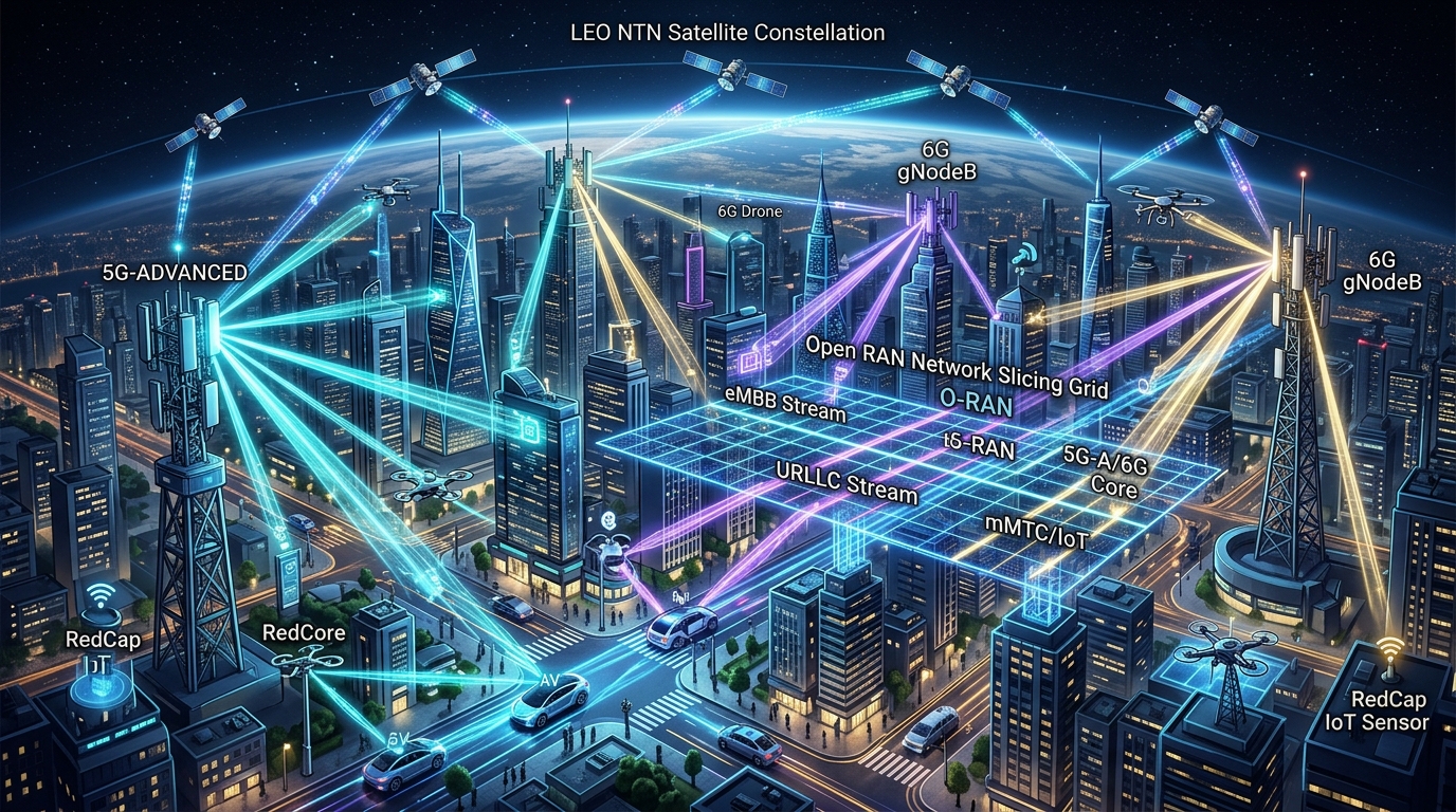
The telecommunications landscape is undergoing a profound structural transformation. While early 5G deployments (3GPP Releases 15 and 16) focused on establishing foundational 5G-NR air interfaces and Standalone (SA) core networks, 5G-Advanced (3GPP Releases 17 and 18) bridges the transition toward the upcoming sixth-generation (6G) era defined under the ITU-R IMT-2030 framework.
5G-Advanced and 6G expand beyond terrestrial cellular footprints to establish 3D Space-Air-Ground Integrated Networks (SAGIN), native Artificial Intelligence air interfaces, extreme energy-efficient architectures, and sub-Terahertz (sub-THz) communication channels capable of Terabit-per-second (Tbps) data rates. The table below delineates this technological progression:
Because physical testbeds for 5G-Advanced and 6G are economically prohibitive and hardware components (like sub-THz radio frequency front-ends and LEO orbital testbeds) are still in experimental development, high-fidelity discrete-event network simulation in ns-3 is the worldwide standard for evaluating these cutting-edge wireless architectures.
2. 5G-LENA & NR Modules: Evaluating 3GPP Rel-17/18 Features
The open-source 5G-LENA module (developed by the Centre Tecnològic de Telecomunicacions de Catalunya – CTTC) serves as the core foundation for 5G cellular modeling in ns-3. Over recent release cycles, researchers have extended 5G-LENA to encompass key Rel-17 and Rel-18 architectural capabilities:
2.1 Reduced Capability (RedCap / NR-Light) IoT Devices
Prior to Rel-17, 5G supported two extreme device categories: high-end eMBB devices (requiring costly multi-antenna modems and gigabit transceivers) and ultra-low-rate narrowband IoT (NB-IoT/LTE-M). This left a critical market void for mid-tier industrial sensors, surveillance cameras, and smart wearables that require 50–150 Mbps throughput with long battery life.
3GPP Rel-17 RedCap resolves this by intentionally downsizing the 5G-NR physical layer:
- Bandwidth Reduction: Maximum operating bandwidth restricted to 20 MHz in FR1 (sub-7 GHz) and 100 MHz in FR2 (mmWave), drastically lowering baseband filter complexity.
- Antenna and MIMO Truncation: Reducing receive antennas from standard 4×4 down to 1T1R or 1T2R configurations.
- Lower Peak Modulation: Capping modulation at 64-QAM (optional 256-QAM in downlink).
- Half-Duplex FDD (HD-FDD): Eliminating expensive duplexer filters by prohibiting simultaneous transmission and reception on paired frequency bands.
- Extended DRX (eDRX) & RRM Relaxation: Allowing devices to enter ultra-deep sleep cycles spanning several hours and relaxing neighbor-cell radio resource management (RRM) measurements when stationary.
In ns-3, RedCap UEs are modeled by extending NrUePhy and configuring custom Bandwidth Part (BWP) managers. By restricting the NrUePhy active resource blocks to 20 MHz and setting antenna dimensions to $1times 2$ in UniformPlanarArray, researchers can simulate the co-existence of 1,000+ RedCap sensors alongside heavy eMBB flows in shared gNB cells, evaluating spectral capacity, scheduler fairness, and battery drain via ns-3’s EnergyModelHelper.
2.2 Advanced Beam Management & Failure Recovery
High-frequency communications in FR2 and sub-THz rely on narrow pencil beams to overcome severe path loss. Rel-17 and Rel-18 introduce agile beam management frameworks modeled across three sequential operational phases:
- P1 Procedure (Coarse Beam Selection): gNodeB sweeps across a broad set of synchronization signal blocks (SSBs) or CSI-RS reference signals, while the UE performs wide-angle scanning to determine the optimal initial beam pair link (BPL).
- P2 Procedure (gNB Beam Refinement): gNodeB tests a localized subset of narrow pencil beams across CSI-RS resources while the UE maintains fixed reception beam parameters.
- P3 Procedure (UE Beam Refinement): gNodeB transmits over a constant beam while the UE steers its internal phased array reception codebook to optimize receive SINR.
- Beam Failure Detection (BFD) & Recovery (BFR): In dynamic mobile scenarios (e.g., a moving vehicular UE or a sudden physical obstacle), the current beam link can collapse instantly. The UE monitors the hypothetical Block Error Rate ($Q_{text{out}}$ threshold). If $N$ consecutive beam failure instances occur, the UE triggers Beam Failure Recovery by sending a contention-free PRACH preamble on a pre-configured candidate beam ($Q_{text{in}}$ threshold), restoring link throughput in under 10 milliseconds.
2.3 Non-Terrestrial Network (NTN) Integration
3GPP Rel-17 formalized the integration of satellite constellations into the 5G cellular core. Unlike legacy proprietary satellite networks, 5G NTN adapts the native 5G-NR physical and MAC layers to communicate with Low Earth Orbit (LEO, 500–1,500 km) and Geostationary Earth Orbit (GEO, ~35,786 km) satellites.
Simulating 5G NTN in ns-3 (using the nr-ntn extension modules) requires resolving severe orbital physics constraints:
- Massive Round-Trip Time (RTT): In LEO constellations, propagation delay alone introduces 10–30 ms one-way delay (20–60 ms RTT), while GEO links exhibit RTTs exceeding 500 ms. Classical 5G HARQ stops transmitting if ACKs are not received within 16 processes. ns-3 NTN modules implement HARQ Disabling or scale HARQ up to 32 concurrent processes to maintain full pipeline saturation.
- Extreme Doppler Shifts: LEO satellites orbit Earth at roughly 7.5 km/s (~27,000 km/h). At Ka-band (20–30 GHz), this induces Doppler frequency shifts up to ±500 kHz and Doppler drift rates exceeding ±3 kHz/s. The ns-3 NTN physical layer incorporates pre-compensation algorithms at the UE and satellite feeder gateway to align carrier frequencies within standard 5G subcarrier spacing (SCS) bounds.
- Regenerative vs. Transparent Payloads: ns-3 allows researchers to simulate both transparent (bent-pipe) satellites (acting as RF transponders reflecting signals to ground base stations) and regenerative satellites (hosting gNB Distributed Units / DUs directly on orbit).
3. Network Slicing & QoS Scheduling: eMBB and URLLC Multiplexing
Network Slicing allows network operators to partition a single shared physical 5G/6G radio access network into multiple isolated, virtualized end-to-end logical networks tailored to diametrically opposed Quality of Service (QoS) requirements:
Enhanced Mobile Broadband (eMBB)
Optimized for massive sustained data volume (4K/8K video streaming, bulk cloud sync). Utilizes large Transport Block Sizes (TBS), deep interleaving, and standard 1 ms slot boundaries with higher-order modulations (up to 4096-QAM).
Ultra-Reliable Low-Latency (URLLC)
Engineered for mission-critical industrial automation, vehicular tele-operation, and remote medical robotics. Demands deterministic latency bounded under 1 millisecond with 99.999% (five-nines) packet delivery reliability.
3.1 SDAP Layer and 5G QoS Flow Mapping
In ns-3 5G-LENA, the Service Data Adaptation Protocol (SDAP) sublayer sits directly above PDCP in the user plane. It maps incoming IP packets from external applications to distinct 5G QoS Flows based on their 5G QoS Identifier (5QI):
- 5QI 80 (eMBB): Non-Guaranteed Bit Rate (Non-GBR), Packet Delay Budget (PDB) = 300 ms, Packet Error Rate (PER) = $10^{-6}$.
- 5QI 82 / 83 (URLLC): Delay Critical GBR, PDB = 10 ms down to 2 ms, PER = $10^{-5}$ with zero queuing backlog tolerance.
The SDAP layer encapsulates each packet with a 1-byte header containing the QoS Flow Identifier (QFI) and dispatches it to the appropriate Data Radio Bearer (DRB) configured in the ns-3 RRC entity.
3.2 MAC Layer Dynamic Preemption and Symbol Puncturing
The primary architectural challenge arises when an unexpected, bursty URLLC packet arrives while the gNB MAC scheduler has already committed the current 1 ms slot to a high-capacity eMBB transmission. If the URLLC packet waits in the queue for the next scheduled slot, its < 1 ms delay budget is violated.
To protect URLLC deadlines, modern 5G-LENA schedulers implement mini-slot preemption (puncturing). The MAC layer halts the ongoing eMBB transmission mid-slot, overrides (punctures) the specific OFDM symbols allocated to eMBB with the high-priority URLLC transport block, and transmits it immediately. To prevent catastrophic eMBB packet corruption, the gNB transmits a Downlink Preemption Indication (DPI) on the DCI, informing the eMBB receiver which code block groups (CBGs) were punctured so that only the corrupted sub-blocks require retransmission.
4. System Architecture: ns-3 Cellular Core & Open RAN (O-RAN) Integration
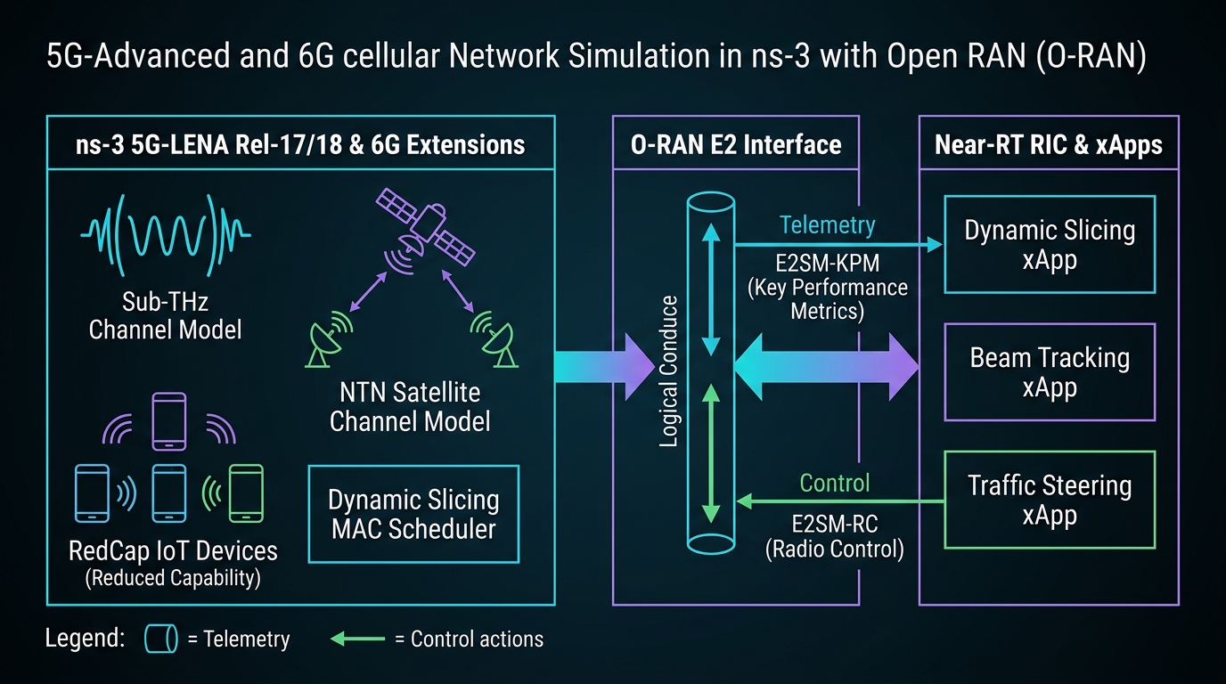
To understand how 5G-Advanced and 6G extensions integrate with disaggregated RAN controllers, examine the architectural diagram below:
5. Sub-THz and mmWave Propagation: Channel Modeling & Beam Tracking
As cellular research transitions into the 6G domain, the operational frequency spectrum scales into the Sub-Terahertz band (100 GHz – 300 GHz), offering vast swaths of contiguous spectrum (multi-GHz channel bandwidths) capable of supporting extreme data density.
5.1 Sub-THz Channel Physics & Molecular Absorption
Radio wave propagation at sub-THz frequencies deviates fundamentally from sub-6 GHz and lower mmWave channels:
- Severe Free-Space Path Loss (FSPL): According to the Friis transmission formula, path loss increases quadratically with carrier frequency:
text{FSPL}(d, f) = 20 log_{10}(d) + 20 log_{10}(f) + 20 log_{10}left(frac{4pi}{c}right)
At 140 GHz, the path loss over a 100-meter distance is roughly 28 dB higher than at 5.8 GHz.
- Molecular Absorption Attenuation: In sub-THz bands, electromagnetic waves collide with resonant gas molecules in the atmosphere (primarily water vapor $H_2O$ and oxygen $O_2$). The total channel transfer function must incorporate frequency-dependent atmospheric attenuation:
L_{text{total}}(d, f) = text{FSPL}(d, f) times exp(kappa(f) cdot d)
Where $kappa(f)$ is the medium absorption coefficient derived from the HITRAN spectroscopic database. Notable resonance peaks occur at 118.7 GHz ($O_2$) and 183.3 GHz ($H_2O$), establishing natural low-loss transmission windows around 140 GHz and 220 GHz.
- Extreme Blockage & Specular Reflection: Sub-THz wavelengths are smaller than 2 millimeters. At this scale, walls and common obstacles act as rough scattering surfaces. Diffuse scattering dominates, diffraction around corners is negligible, and human body blockages induce deep shadow fades exceeding 30–45 dB. Communication is practically limited to Line-of-Sight (LoS) or first-order specular reflected paths.
5.2 Ultra-Massive MIMO (UM-MIMO) & High-Frequency Beam Tracking
To overcome extreme path loss, sub-THz transceivers pack thousands of tiny patch antennas into compact physical footprints (e.g., a $64times 64$ element array occupying only a few square centimeters). These arrays generate razor-sharp “pencil beams” with antenna gains exceeding 30 dBi.
However, pencil beams suffer from extreme sensitivity to user mobility. A minor rotational head tilt by a VR user or an accelerating vehicle displaces the pencil beam outside the main radiation lobe, triggering immediate link blackout. In ns-3, researchers simulate Extended Kalman Filter (EKF)-based predictive beam tracking, where the gNB continuously tracks UE spatial motion vectors and pre-steers beam directions before physical signal degradation occurs.
6. Open RAN (O-RAN) Integration: Controlling ns-3 Cellular Nodes via Near-RT RIC
One of the most consequential architectural movements in modern telecommunications is the Open RAN (O-RAN) Alliance. O-RAN disaggregates the monolithic proprietary base station into interoperable, multi-vendor components: the Open Central Unit (O-CU), Open Distributed Unit (O-DU), Open Radio Unit (O-RU), and the Near-Real-Time RAN Intelligent Controller (Near-RT RIC).
6.1 The E2 Telemetry & Control Interface in ns-3
The Near-RT RIC executes intelligent control loops operating within timescales of 10 ms to 1000 ms. It connects to cellular nodes through the standardized E2 interface. In research simulations, tools like ns3-oran or SCORe embed an E2 Agent directly inside ns-3’s gNodeB architecture:
- E2SM-KPM (Key Performance Metrics Service Model): The ns-3 E2 Agent samples internal PHY/MAC/RLC metrics (such as PRB utilization per slice, average CQI, buffer backlog, packet delay distributions, and UE throughput) and encapsulates them into ASN.1 or Google Protobuf messages. These telemetry streams are transmitted over ZeroMQ or SCTP sockets to the external Near-RT RIC.
- E2SM-RC (RAN Control Service Model): When an intelligence algorithm (xApp) running on the Near-RT RIC detects SLA degradation or suboptimal spectrum distribution, it dispatches an E2 Control message back to the ns-3 E2 Agent. The agent immediately applies the control action—reconfiguring the MAC scheduler’s slice quota weights, triggering an inter-cell handover, or adjusting beamforming matrices in real time.
6.2 Reinforcement Learning xApps in Action
By connecting ns-3 to real-world open-source RIC platforms (such as the O-RAN Software Community / OSC RIC or ONOS RIC), researchers evaluate production-grade microservice applications called xApps:
- Dynamic Slicing xApp: Employs Deep Reinforcement Learning (PPO or SAC) to optimize PRB quotas between competing eMBB and URLLC slices every 100 ms, satisfying URLLC delay bounds while maximizing revenue throughput on the eMBB slice.
- Intelligent Traffic Steering xApp: Dynamically offloads UEs between terrestrial macro gNodeBs, mmWave small cells, and LEO satellite NTN relays based on predicted mobility trajectories and link qualities.
7. Complete C++ Simulation Blueprint in ns-3
Below is a production-grade C++ simulation script demonstrating how to instantiate a 5G-Advanced cellular network in ns-3 (using 5G-LENA), configuring FR2 mmWave carrier frequencies, beamforming helpers, and multiple QoS traffic classes (eMBB and URLLC):
#include “ns3/core-module.h”
#include “ns3/network-module.h”
#include “ns3/mobility-module.h”
#include “ns3/nr-module.h”
#include “ns3/point-to-point-module.h”
#include “ns3/internet-module.h”
using namespace ns3;
int main(int argc, char *argv[]) {
CommandLine cmd(__FILE__);
cmd.Parse(argc, argv);
// 1. Create Core Network Nodes and Helpers
Ptr
Ptr
Ptr
nrHelper->SetEpcHelper(epcHelper);
nrHelper->SetBeamformingHelper(beamformingHelper);
// 2. Configure FR2 mmWave Spectrum (28 GHz with 100 MHz Bandwidth, Numerology mu=3)
CcBwpCreator ccBwpCreator;
CcBwpCreator::SimpleOperationBandConf bandConf(28.0e9, 100.0e6, 1, BandwidthPartInfo::UMa);
OperationBandInfo band = ccBwpCreator.CreateOperationBandContiguousCc(bandConf);
nrHelper->InitializeOperationBand(&band);
// 3. Configure Phased Array Antennas (8×8 gNB array, 2×2 UE array)
nrHelper->SetGnbPhyAttribute(“TxPower”, DoubleValue(30.0)); // 30 dBm
nrHelper->SetGnbAntennaAttribute(“NumRows”, UintegerValue(8));
nrHelper->SetGnbAntennaAttribute(“NumColumns”, UintegerValue(8));
nrHelper->SetUeAntennaAttribute(“NumRows”, UintegerValue(2));
nrHelper->SetUeAntennaAttribute(“NumColumns”, UintegerValue(2));
// 4. Create Node Containers
NodeContainer gnbNodes;
gnbNodes.Create(1);
NodeContainer ueNodes;
ueNodes.Create(10); // Mixed eMBB and URLLC UEs
// 5. Install Mobility
MobilityHelper mobility;
mobility.SetMobilityModel(“ns3::ConstantPositionMobilityModel”);
mobility.Install(gnbNodes);
mobility.SetPositionAllocator(“ns3::GridPositionAllocator”,
“MinX”, DoubleValue(10.0), “DeltaX”, DoubleValue(5.0),
“MinY”, DoubleValue(10.0), “DeltaY”, DoubleValue(5.0),
“GridWidth”, UintegerValue(5), “LayoutType”, StringValue(“RowFirst”));
mobility.Install(ueNodes);
// 6. Install 5G NetDevices onto Nodes
NetDeviceContainer gnbNetDev = nrHelper->InstallGnbDevice(gnbNodes, band);
NetDeviceContainer ueNetDev = nrHelper->InstallUeDevice(ueNodes, band);
// 7. Attach UEs to gNodeB
nrHelper->AttachToClosestGnb(ueNetDev, gnbNetDev);
Simulator::Stop(Seconds(10.0));
Simulator::Run();
Simulator::Destroy();
return 0;
}
8. Synthesis & The Road to 6G Commercialization
The journey from 5G-Advanced to 6G represents a fundamental rethinking of wireless systems architecture. The cellular network is evolving from a rigid, monolithic communication conduit into an intelligent, disaggregated, multi-dimensional compute-and-connectivity fabric.
Through ns-3 and its expansive 5G-LENA ecosystem, researchers and telecommunications engineers possess an open, mathematically rigorous platform capable of evaluating every dimension of this frontier: from RedCap IoT battery sustainability and Non-Terrestrial Network Doppler compensation to microsecond URLLC preemption, sub-THz molecular absorption dynamics, and closed-loop Open RAN control. Mastering these simulation methodologies is the indispensable gateway to shaping the future of global wireless communications.
Written by Charles Pandian
Cellular systems researcher and network simulation architect specializing in ns-2, ns-3, 5G-NR/5G-Advanced modeling, Open RAN (O-RAN) interfaces, and 6G sub-THz propagation. Regular contributor to ProjectGuideline.com academic guides and simulation architectures.
 Take Me to Afarion ns-3 iPlayground