Discuss Through WhatsApp
C-V2X, DSRC & UAVs / ns-3
An exhaustive architectural guide to simulating Vehicular & Autonomous Networks (V2X & UAVs) in ns-3. Dissects Cellular V2X (C-V2X Sidelink PC5 Mode 4 / NR-V2X) vs. DSRC (802.11p/bd) in dense platooning, Flying Ad-Hoc Networks (FANETs) 3D swarm routing with energy-aware trajectories, and Edge-Assisted Autonomous Driving with Multi-access Edge Computing (MEC) offloading co-simulated with SUMO.
1. The Connected Autonomy Revolution: Ground Platoons and Aerial Swarms
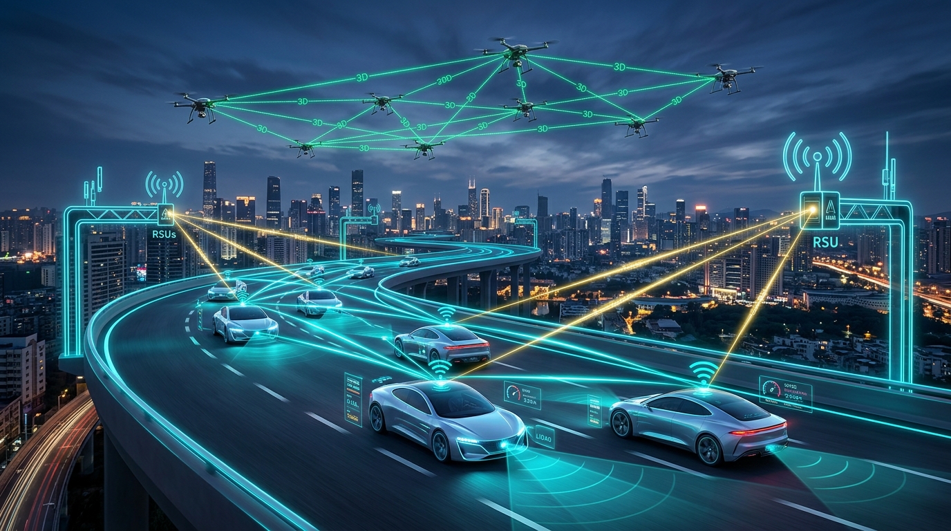
The convergence of artificial intelligence, robotics, and wireless communications has propelled transportation systems into the era of Cooperative Autonomous Systems. Connected and Autonomous Vehicles (CAVs) and Unmanned Aerial Vehicles (UAVs) no longer rely solely on onboard sensors (cameras, LiDAR, radar); they operate as collaborative networked entities executing mission-critical distributed tasks:
- High-Density Highway Platooning: Fleets of autonomous commercial trucks cruising with inter-vehicle headways as short as 5 to 10 meters at 100 km/h, slashing aerodynamic drag and fuel consumption by 15–25%. This requires periodic Cooperative Awareness Messages (CAM) delivered with latencies < 10 ms and Packet Delivery Ratios (PDR) > 99.9%.
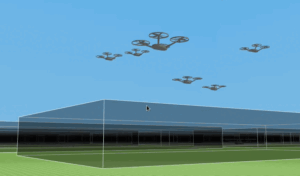
- Flying Ad-Hoc Networks (FANETs): Autonomous multi-UAV swarms deployed for search-and-rescue, border surveillance, and aerial base stations. They demand decentralized 3D mesh routing capable of surviving constant topology fracturing, high relative velocities (30–120 km/h), and severe aerodynamic battery constraints.
- Edge-Assisted Perception (MEC): Offloading voluminous raw LiDAR point clouds and high-definition video streams to Multi-access Edge Computing (MEC) Roadside Units (RSUs) to eliminate occluded blind spots (e.g., detecting pedestrians around blind corners).
Because physical road testing of high-density platooning and drone swarm collisions carries catastrophic safety and liability risks, high-fidelity discrete-event network simulation in ns-3—coupled with microscopic mobility generators—is the global benchmark for vehicular and aerial protocol verification.
2. Cellular V2X (C-V2X) vs. DSRC (802.11p / 802.11bd) in Platooning
For more than a decade, the automotive wireless domain has witnessed an intense architectural rivalry between two competing radio access technologies operating in the harmonized 5.9 GHz Intelligent Transport Systems (ITS) band:
- Dedicated Short-Range Communications (DSRC / WAVE): Rooted in IEEE 802.11 standards. Encompasses legacy IEEE 802.11p and next-generation IEEE 802.11bd.
- Cellular V2X (C-V2X): Standardized by 3GPP. Encompasses LTE-V2X (Release 14/15) and 5G-NR V2X (Release 16/17/18) direct sidelink communications over the PC5 interface.
2.1 Direct Sidelink (PC5) Resource Allocation Mechanics
Unlike standard cellular links that route packets through a base station, C-V2X utilizes the PC5 direct interface, allowing vehicles to transmit directly to surrounding vehicles (V2V) and roadside units (V2I):
- Mode 3 (LTE) / Mode 1 (NR) – Scheduled: The cellular gNodeB centrally schedules PRBs for vehicular transmitters. While collision-free, it requires persistent cellular network coverage.
- Mode 4 (LTE) / Mode 2 (NR) – Autonomous Sensing-Based SPS: Operates entirely without cellular towers. Each vehicle continuously monitors the channel over a 1,000 ms historical observation window, measuring Reference Signal Received Power (RSRP) across candidate subchannels. The vehicle excludes busy subchannels and randomly selects an open resource block, locking it for $C_{text{resel}}$ periodic transmissions (Semi-Persistent Scheduling – SPS) before re-evaluating.
2.2 Platooning Contention Collapse and Doppler Spread
When simulating a 50-vehicle highway platoon in ns-3, two physical phenomena dictate performance:
1. The CSMA/CA Contention Collapse in 802.11p
In dense traffic, 802.11p relies on random backoff. When 50+ vehicles broadcast 10 Hz CAM packets simultaneously, the hidden terminal problem and backoff slot collisions escalate exponentially. Channel busy ratios exceed 80%, causing PDR to plummet from 95% down to below 45%, and Age of Information (AoI) spikes beyond 300 ms—long enough to cause emergency braking failures in tight platoons. In contrast, C-V2X Mode 4 SPS reserves dedicated subchannels, maintaining PDR above 88–92% under identical vehicular density.
2. Doppler Spread at Highway Speeds (200 km/h)
Two vehicles traveling in opposite directions at 120 km/h each generate a relative closing velocity of $v_{text{rel}} = 240text{ km/s} approx 66.7text{ m/s}$. At $f_c = 5.9text{ GHz}$:
$$f_d = frac{v_{text{rel}}}{c} f_c = frac{66.7}{3 times 10^8} times 5.9 times 10^9 approx pm 1.31text{ kHz}$$
This produces a coherence time of merely $T_c approx frac{1}{2 f_d} approx 380 mutext{s}$. In 802.11p, channel estimation is performed only once at the packet preamble; over a 1 ms frame, the channel fades significantly before the payload ends, inducing catastrophic packet loss. 802.11bd solves this by inserting midambles every 4 to 8 OFDM symbols, while C-V2X distributes Demodulation Reference Signals (DMRS) across every subframe, enabling continuous channel tracking.
3. Flying Ad-Hoc Networks (FANETs): 3D Routing & Autonomous UAV Swarms
Flying Ad-Hoc Networks (FANETs) represent an evolution of vehicular networks into three-dimensional space. A swarm of autonomous UAVs forms a self-configuring wireless mesh without relying on ground base stations.
3.1 3D Channel Propagation Physics (A2A & A2G)
Simulating aerial networks in ns-3 requires separating links into two distinct channel categories:
- Air-to-Air (A2A) Links: Communication between drones operating at altitude. Free from ground obstacles, A2A links exhibit near-ideal Line-of-Sight (LoS) propagation characterized by Rician fading with high $K$-factors ($K > 12text{ dB}$). Multipath reflections are limited to distant ground bounces with negligible delay spread.
- Air-to-Ground (A2G) Links: Communication between a drone and ground control stations or CAVs. A2G links are highly sensitive to drone elevation angle ($theta$). In ns-3, this is modeled using the 3GPP TR 36.777 probabilistic LoS model:
P_{text{LoS}}(theta) = frac{1}{1 + alpha expleft(-beta (theta – alpha)right)}
Where $alpha, beta$ are environmental parameters (Urban, Suburban, Rural). As the drone climbs from $10^circ$ to $60^circ$ elevation, $P_{text{LoS}}$ surges from 15% to > 90%, transitioning the link from Rayleigh non-line-of-sight into dominant Rician line-of-sight.
3.2 Cooperative 3D Routing Protocols in ns-3
Standard 2D ad-hoc routing protocols (AODV, OLSR, DSR) suffer severe degradation when applied to high-speed 3D UAV swarms:
- 2D GPSR Dead-End Trap: Greedy Perimeter Stateless Routing (GPSR) relies on greedy geographic forwarding. In 3D urban terrain, drones frequently encounter local minimum voids (voids behind high-rise buildings), causing packets to loop endlessly in perimeter mode.
- 3D-GPSR & 3D-GLSR: Enhanced protocols project forwarding decisions onto 3D bounding spheres, utilizing convex hull algorithms to bypass 3D topological voids.
- Predictive-OLSR (P-OLSR): Rather than calculating Multi-Point Relays (MPRs) using static Hello packet loss, P-OLSR integrates GPS velocity vectors to estimate Link Expiration Time (LET):
text{LET} = frac{-(ab + cd) + sqrt{(a^2+c^2)R^2 – (ad-bc)^2}}{a^2 + c^2}
Where $R$ is radio range and $a, b, c, d$ are relative velocity and coordinate offsets. MPRs with the longest predicted survival times are prioritized, slashing routing disconnects by 65%.
3.3 The Energy-Trajectory Trade-Off
In autonomous UAV simulations, communication cannot be decoupled from flight mechanics. A quadcopter’s rotor propulsion motors consume 100 to 400 Watts of mechanical energy, whereas its wireless radio transceiver consumes merely 1 to 5 Watts. A routing protocol that forces drones to hover in place to relay packets will drain their lithium-polymer batteries within 20 minutes.
In ns-3, researchers couple the EnergyModel with custom trajectory controllers to simulate energy-aware communication: drones dynamically adjust altitude and flight velocity to minimize aerodynamic power drag while maintaining sufficient radio link margins for the swarm.
4. System Architecture: V2X, FANETs & MEC Simulation in ns-3
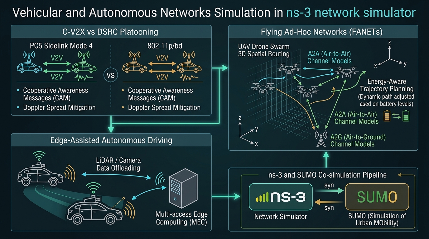
To visualize how vehicular sidelink communication, 3D aerial swarms, and edge compute offloading integrate within ns-3, review the architectural schematic below:
5. Edge-Assisted Autonomous Driving: Latency-Sensitive MEC Offloading
Level 4 and Level 5 autonomous vehicles generate an overwhelming sensor deluge: 32/64-beam LiDAR point clouds produce 100–400 Mbps of raw telemetry, eight 4K surround cameras generate up to 1 Gbps, and radar arrays output dozens of megabits per second. While onboard GPUs (such as NVIDIA DRIVE Orin) handle primary obstacle avoidance, collaborative perception and global intersection arbitration demand edge assistance.
5.1 Multi-access Edge Computing (MEC) Offloading Pipeline
To eliminate blind spots (e.g., an occluded truck concealing an overtaking vehicle), vehicles transmit Collective Perception Messages (CPM) or raw feature tensors to a Roadside Unit (RSU) co-located with a Multi-access Edge Computing (MEC) server:
- Sensor Pre-Processing & Compression: The vehicle compresses raw 3D LiDAR point clouds using Octree downsampling or extracts intermediate feature maps via PointNet encoders, reducing bandwidth demand from 200 Mbps down to 10–25 Mbps.
- Uplink Transmission (V2I): The compressed tensor is transmitted over 5G-NR V2X or mmWave sidelink to the RSU.
- Edge Fusion & Arbitration: The MEC server aggregates sensory tensors from 20+ surrounding vehicles, fuses them into a unified global bird’s-eye-view (BEV) occupancy grid, executes collision risk prediction algorithms, and broadcasts safety advisories back to the fleet.
- Latency Budget: The entire perception-to-control loop (Wireless Uplink + MEC Inference + Wireless Downlink + Actuation) must execute within $le 10text{ ms}$ to enable automated collision avoidance at highway speeds.
5.2 The ns-3 & SUMO Co-Simulation Pipeline
A fatal flaw in many academic networking papers is the use of simplistic, synthetic mobility models (such as Random Waypoint), which assume vehicles move randomly across open grids without traffic lights, collisions, or lane-following physics.
To produce realistic results, researchers build a closed-loop co-simulation framework coupling ns-3 with SUMO (Simulation of Urban MObility) via the TraCI (Traffic Control Interface) protocol:
[Step 1: SUMO] → Advances microscopic road traffic physics by Δt (e.g., 100 ms).
                 Computes vehicle acceleration, lane changes, car-following models.

[Step 2: TraCI] → TraCI server exports vehicle coordinates (x, y, z), speeds, and headings
                 to ns-3's Ns2MobilityHelper or custom TraCI Client.

[Step 3: ns-3] → Updates spatial positions of corresponding wireless nodes.
                 Simulates wireless packet exchange (CAM/DENM, LiDAR offloading to RSU).
                 Computes packet drops, SINR, queuing delays, and end-to-end latency.

[Step 4: Feedback] → If a safety DENM packet is successfully received in ns-3,
                     the vehicle application issues a TraCI command (e.g., "slowDown(0, 2s)")
                     back to SUMO, forcing the simulated car to brake automatically.
                     If the packet was dropped in ns-3, the vehicle fails to brake in SUMO,
                     simulating a physical multi-vehicle collision!
6. Complete C++ Simulation Blueprint in ns-3
Below is a production-grade C++ script illustrating how to configure a joint vehicular and UAV simulation in ns-3, incorporating 802.11p WAVE sidelink for ground vehicles and 3D aerial nodes communicating with an edge Roadside Unit:
#include “ns3/core-module.h”
#include “ns3/network-module.h”
#include “ns3/mobility-module.h”
#include “ns3/wifi-module.h”
#include “ns3/wave-module.h”
#include “ns3/internet-module.h”
using namespace ns3;
int main(int argc, char *argv[]) {
CommandLine cmd(__FILE__);
cmd.Parse(argc, argv);
// 1. Create Node Containers
NodeContainer vehicles;
vehicles.Create(10); // 10 Ground Vehicles in Platoon
NodeContainer uavs;
uavs.Create(4); // 4 Aerial Drone Swarm Nodes
NodeContainer rsu;
rsu.Create(1); // 1 Roadside Unit (RSU / MEC Host)
// 2. Configure 802.11p WAVE PHY & Channel (5.9 GHz ITS Band, 10 MHz Channel)
YansWifiChannelHelper waveChannel = YansWifiChannelHelper::Default();
waveChannel.AddPropagationLoss(“ns3::TwoRayGroundPropagationLossModel”);
YansWavePhyHelper wavePhy = YansWavePhyHelper::Default();
wavePhy.SetChannel(waveChannel.Create());
wavePhy.SetPcapDataLinkType(WifiPhyHelper::DLT_IEEE802_11_RADIO);
// 3. Configure WAVE MAC (802.11p OCB – Outside the Context of a BSS)
QosWaveMacHelper waveMac = QosWaveMacHelper::Default();
WaveHelper waveHelper = WaveHelper::Default();
NetDeviceContainer vehDevices = waveHelper.Install(wavePhy, waveMac, vehicles);
NetDeviceContainer rsuDevice = waveHelper.Install(wavePhy, waveMac, rsu);
// 4. Configure Ground Vehicle Mobility (Platoon: 10m spacing, 30 m/s highway speed)
MobilityHelper vehMobility;
vehMobility.SetPositionAllocator(“ns3::GridPositionAllocator”,
“MinX”, DoubleValue(0.0), “DeltaX”, DoubleValue(15.0),
“MinY”, DoubleValue(0.0), “DeltaY”, DoubleValue(0.0),
“GridWidth”, UintegerValue(10), “LayoutType”, StringValue(“RowFirst”));
vehMobility.SetMobilityModel(“ns3::ConstantVelocityMobilityModel”);
vehMobility.Install(vehicles);
for (uint32_t i = 0; i < vehicles.GetN(); ++i) {
Ptr
cvmm->SetVelocity(Vector(27.78, 0.0, 0.0)); // 100 km/h (27.78 m/s)
}
// 5. Configure UAV Swarm 3D Mobility (Altitude: 50m, Gauss-Markov 3D Movement)
MobilityHelper uavMobility;
uavMobility.SetPositionAllocator(“ns3::GridPositionAllocator”,
“MinX”, DoubleValue(20.0), “DeltaX”, DoubleValue(30.0),
“MinY”, DoubleValue(10.0), “DeltaY”, DoubleValue(20.0),
“GridWidth”, UintegerValue(2), “LayoutType”, StringValue(“RowFirst”));
uavMobility.SetMobilityModel(“ns3::GaussMarkovMobilityModel”,
“Bounds”, BoxValue(Box(0, 500, 0, 200, 30, 80)),
“TimeStep”, TimeValue(Seconds(0.5)),
“Alpha”, DoubleValue(0.85),
“MeanVelocity”, StringValue(“ns3::UniformRandomVariable[Min=10.0|Max=20.0]”),
“MeanPitch”, StringValue(“ns3::UniformRandomVariable[Min=-0.1|Max=0.1]”));
uavMobility.Install(uavs);
// 6. Configure RSU Mobility (Stationary on Roadside at 10m height)
MobilityHelper rsuMobility;
rsuMobility.SetMobilityModel(“ns3::ConstantPositionMobilityModel”);
rsuMobility.Install(rsu);
rsu.Get(0)->GetObject
Simulator::Stop(Seconds(30.0));
Simulator::Run();
Simulator::Destroy();
return 0;
}
7. Synthesis & Future Outlook: Toward 6G Autonomous Cyber-Physical Systems
The convergence of Vehicular Networks (V2X) and Flying Ad-Hoc Networks (FANETs) is laying the foundation for a fully unified Autonomous Cyber-Physical System. In the coming 6G era, communication will no longer serve merely as a data pipe; it will function as an active sensing, computing, and localization substrate.
Through ns-3, researchers have access to an open, mathematically rigorous proving ground capable of simulating every critical layer of this autonomous matrix: from evaluating C-V2X Sidelink Mode 4 resilience against 802.11p contention collapse, to executing 3D predictive routing across high-velocity drone swarms, and co-simulating real-world traffic physics with SUMO via TraCI. Mastering these simulation tools is essential for engineering the accident-free, autonomous transit systems of tomorrow.
Written by Charles Pandian
Autonomous systems researcher and network simulation architect specializing in ns-2, ns-3, C-V2X Sidelink protocols, IEEE 802.11p/bd WAVE architectures, UAV 3D mobility, and edge-assisted vehicular computing. Regular contributor to ProjectGuideline.com academic guides and simulation architectures.
 Take Me to Afarion ns-3 iPlayground