Discuss Through WhatsApp
3GPP Rel-17/18 NTN & LEO
A comprehensive engineering guide to simulating Non-Terrestrial Networks (NTN) and Low Earth Orbit (LEO) Satellite Megaconstellations using ns-3. This guide breaks down Dynamic Inter-Satellite Link (ISL) routing across orbital planes, Seamless Ground-to-Satellite Handover & Doppler shift mitigation, and Direct-to-Cellular (D2C / Direct-to-Device) 5G-NR physical and MAC layer adaptations for standard mobile handhelds.
1. The Orbital Frontier: Integrating Satellite Constellations with 5G and 6G
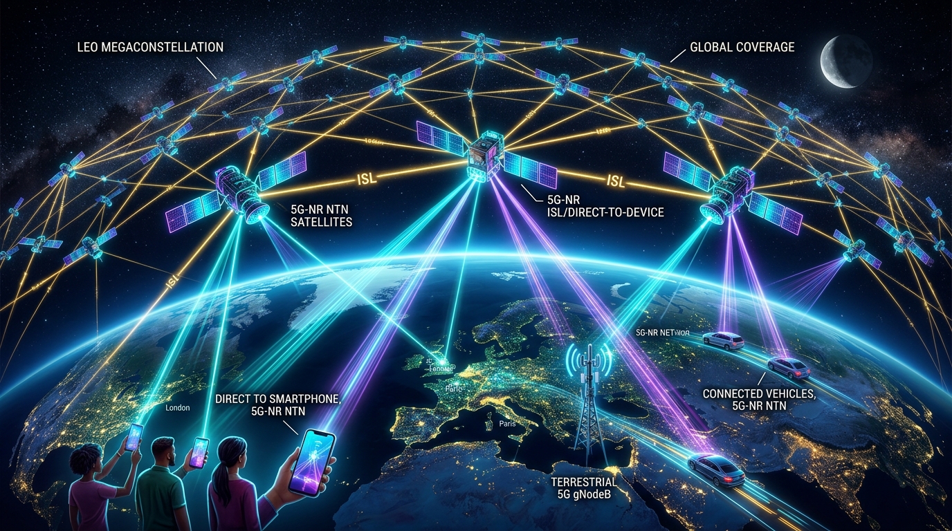
Despite decades of massive capital expenditure in terrestrial cellular infrastructure, ground-based cellular networks cover less than 20% of the Earth’s landmass and less than 5% of the total planetary surface. The oceans, polar regions, airspace corridors, deserts, and remote rural territories remain severe communication dead zones.
To establish ubiquitous global connectivity, the telecommunications industry has pivoted toward Non-Terrestrial Networks (NTN), spearheaded by commercial Low Earth Orbit (LEO) megaconstellations such as SpaceX Starlink, Amazon Project Kuiper, Eutelsat OneWeb, and Telesat Lightspeed. Concurrently, the 3GPP has integrated satellite links directly into the global cellular mainstream:
- 3GPP Release 17 (The NTN Foundation): Formally standardized 5G-NR support for non-terrestrial platforms across both FR1 (S-band: ~2 GHz) and FR2 (Ka-band: 20–30 GHz), defining orbital timing advance, Doppler pre-compensation, and extended HARQ process timelines.
- 3GPP Release 18 (5G-Advanced NTN): Introduced coverage enhancements for handheld devices, network-based positioning, regenerative satellite payloads, and 1024-QAM downlink modulations.
- 3GPP Release 19 & 6G (Direct-to-Cellular & SAGIN): Solidifies Direct-to-Cellular (D2C) connectivity for unmodified mass-market smartphones and establishes the blueprint for 6G Space-Air-Ground Integrated Networks (SAGIN).
Because deploying and testing orbital hardware incurs astronomical launch costs and orbital risks, high-fidelity discrete-event network simulation in ns-3 is the indispensable platform for modeling constellation mechanics, evaluating dynamic routing protocols, and validating 5G-NR NTN protocol stacks.
2. LEO Megaconstellation Routing: Dynamic Inter-Satellite Links (ISL)
Unlike Geostationary Earth Orbit (GEO) satellites that remain fixed relative to a point on the equator at 35,786 km, Low Earth Orbit (LEO) satellites circle the planet at altitudes between 500 km and 1,500 km with orbital velocities exceeding 7.5 km/s (27,000 km/h), completing a full orbit every 90 to 110 minutes.
In modern megaconstellations, satellites do not act as isolated relays; they form an autonomous, distributed space mesh network interconnected via high-speed optical (laser) Inter-Satellite Links (ISLs) operating at 10 to 100 Gbps.
2.1 Constellation Geometry: Walker Delta vs. Walker Star
The network topology of a LEO megaconstellation is dictated by its orbital mechanics:
- Walker Delta Constellations (e.g., SpaceX Starlink Phase 1): Satellites are distributed across inclined circular orbits (e.g., $53^circ$ inclination). Satellites travel in parallel directions across mid-latitudes, maintaining relatively stable inter-plane link geometry.
- Walker Star / Polar Constellations (e.g., OneWeb, Iridium): Satellites travel in near-polar orbits ($86^circ–90^circ$ inclination). While this guarantees 100% polar coverage, it creates two major routing anomalies:
1. The Orbital Seam: The counter-rotating boundary where planes 1 and $N$ travel in opposite directions with relative closing speeds exceeding 15 km/s, making inter-plane laser tracking virtually impossible.
2. Polar Convergence: Orbital planes converge near the north and south poles, forcing inter-plane laser links to disconnect or power down due to extreme angular velocity changes.
2.2 The Physics of Intra-Orbit vs. Inter-Orbit ISLs
A typical LEO satellite houses four optical communication terminals (OCTs):
- Intra-Orbit ISLs (2 links): Pointing to the satellite directly ahead and behind in the exact same orbital plane. The distance between intra-orbit neighbors remains virtually constant ($Delta d approx 0$), resulting in permanent, static, low-jitter point-to-point connections.
- Inter-Orbit ISLs (2 links): Pointing to adjacent orbital planes to the left and right. The distance and angle between adjacent plane satellites continuously oscillate as they orbit from the equator toward the poles. Over polar regions, inter-plane ISLs must be intentionally severed and dynamically re-established on the descent, creating a Time-Varying Graph (TVG) topology.
2.3 Space Mesh Routing Protocols in ns-3
Classical terrestrial routing protocols (such as OSPF, IS-IS, or BGP) fail catastrophically in LEO megaconstellations:
- Signaling Storms: Flooding link-state advertisements (LSAs) every time an inter-plane ISL disconnects or reconnects over polar zones consumes excessive space link bandwidth.
- Route Flapping & Convergence Delays: By the time Dijkstra’s algorithm converges on thousands of space routers, the orbital positions have already shifted, producing persistent micro-loops and black holes.
1. Contact Graph Routing (CGR): Because orbital mechanics are mathematically deterministic via Keplerian elements and SGP4 propagation models, future ISL connection schedules (“contact plans”) are calculated offline days in advance. ns-3 nodes use pre-computed contact matrices to route packets without reactive control plane flooding.
2. Segment Routing over IPv6 (SRv6): Ground ingress gateways inspect the deterministic satellite ephemeris, compute optimal shortest-path label stacks across the space mesh, and encode the exact orbital hops into the IPv6 header, removing routing table computation from the satellite CPU entirely.
3. Geographical / Greedy Grid Routing: Leveraging the regular Manhattan-like torus grid of LEO shells to route packets purely based on Cartesian spatial coordinates towards the destination ground station.
3. Seamless Ground-to-Satellite Handover & Doppler Shift Mitigation
Connecting ground terminals to satellites traveling at 27,000 km/h introduces severe radio propagation challenges fundamentally alien to static terrestrial cell towers.
3.1 Doppler Shift Physics and Dynamic Pre-Compensation
When a LEO satellite approaches a ground user, the relative radial velocity compresses the emitted electromagnetic waves, shifting the perceived carrier frequency upward. As the satellite recedes toward the opposite horizon, the frequency drops:
Where $v_{text{sat}}$ is orbital speed, $theta(t)$ is the elevation angle, and $f_c$ is the carrier frequency.
Max Doppler Shift: ± 48 kHz
Max Doppler Drift Rate: ∼ 550 Hz / s
SCS Subcarrier Spacing: 15 kHz or 30 kHz
Impact: Doppler exceeds subcarrier width (3.2x SCS)! Total inter-carrier interference (ICI) without compensation.
Max Doppler Shift: ± 670 kHz
Max Doppler Drift Rate: ∼ 7.7 kHz / s
SCS Subcarrier Spacing: 60 kHz or 120 kHz
Impact: Massive frequency drift requires continuous real-time baseband pre-tracking.
Doppler Mitigation in ns-3: 3GPP Rel-17 specifies GNSS-assisted frequency pre-compensation. Because both the user’s GPS position and the satellite’s ephemeris are known, the UE calculates the expected Doppler curve and shifts its local oscillator before transmitting on the uplink. In the downlink, the satellite pre-compensates the beam center frequency, leaving only a minor residual Doppler offset that standard 5G Phase Tracking Reference Signals (PTRS) easily eliminate.
3.2 Handover Dynamics in LEO Constellations
In terrestrial cellular, handovers occur when a user physically moves from one cell tower coverage zone to another (timescale of minutes to hours). In LEO networks, the user is stationary, but the base station flies overhead at mach-22:
- Fleeting Visibility Windows: A single LEO satellite remains visible above a $10^circ$ elevation threshold for merely 5 to 10 minutes.
- Spot Beam Handovers: Each satellite projects dozens of narrow phased-array spot beams onto the ground. An individual beam sweeps over a ground user in 15 to 45 seconds. A connected terminal undergoes continuous intra-satellite beam handovers followed by inter-satellite handovers.
- The Failure of Classical A3 Events: In standard 3GPP Event A3, handover is triggered when neighbor cell RSRP exceeds serving cell RSRP by a hysteresis offset for a Time-to-Trigger ($TTT$). Because satellite RSRP degrades rapidly as it dips toward the horizon, setting standard TTT values results in either premature ping-pong handovers or Radio Link Failure (RLF) before the handover command completes.
In ns-3 NTN simulations, researchers implement 3GPP Conditional Handover (CHO). The serving satellite pre-configures execution conditions on the UE (based on deterministic satellite elevation angle or remaining visibility timer) long before signal degradation. When the time condition triggers, the UE executes immediate, autonomous handover to the ascending satellite without waiting for real-time RRC signaling handshakes across the long space-ground delay path.
4. System Architecture: NTN Simulation Pipeline in ns-3
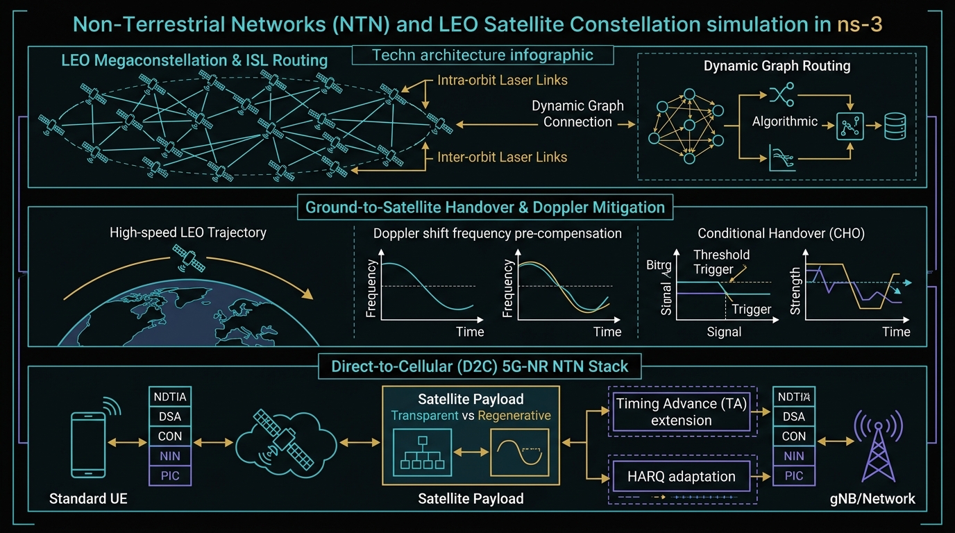
To understand the end-to-end integration between orbital physics, ISL mesh routing, and the 5G-NR NTN protocol stack, inspect the architectural diagram below:
5. Direct-to-Cellular (D2C) Simulation: Standard Handhelds to Space
The most revolutionary application in modern wireless is Direct-to-Cellular (D2C / Direct-to-Device). Unlike legacy satellite phone services (Iridium, Inmarsat) that required specialized bulky hardware with prominent external antennas, D2C enables standard, unmodified consumer smartphones (e.g., iPhone, Samsung Galaxy) to communicate directly with satellites from remote wilderness, oceans, or natural disaster zones.
5.1 The Brutal Physical Link Budget Challenge
Bridging a 600 km space link with an ordinary smartphone pushes the laws of physics to their absolute limits:
Because the smartphone cannot increase its transmit power or deploy a directional dish, the burden of physics is entirely shifted onto the satellite. Satellites providing D2C connectivity (such as AST SpaceMobile’s BlueBird or Starlink V2 Mini D2C) deploy massive phased array apertures spanning tens of square meters to synthesize hundreds of high-gain, narrow spot beams capable of detecting microwatt smartphone transmissions.
5.2 Transparent (Bent-Pipe) vs. Regenerative Satellite Payloads
In ns-3, researchers evaluate two competing payload architectures:
Transparent (Bent-Pipe) Payload
The satellite operates as a pure analog RF frequency converter and amplifier. It receives S-band signals from the smartphone, translates them to Ka-band feeder links, and reflects them down to a ground gateway base station.
Trade-off: Simpler, lighter satellite hardware. However, it incurs double propagation delay (User → Satellite → Gateway → Satellite → User) and requires a ground gateway within the satellite’s immediate geographic footprint.
Regenerative (On-Board Processing) Payload
The satellite hosts the full 5G gNodeB base station (or gNB-DU) on orbit. It demodulates, decodes, and processes 5G-NR frames locally in space.
Trade-off: Requires space-hardened radiation-tolerant compute hardware. However, it cuts round-trip latency in half, enables direct satellite-to-satellite ISL routing, and provides true autonomous connectivity over remote oceans without requiring local ground gateways.
5.3 3GPP Rel-17/18 MAC Layer Protocol Adaptations
Deploying standard 5G-NR over non-terrestrial links breaks several core assumptions of terrestrial cellular MAC:
- Extended Timing Advance (TA): In terrestrial cells (radius ≤ 10 km), the Round-Trip Time varies by at most 66 $mutext{s}$. In LEO NTN spot beams spanning 50 to 100 km, the differential delay between cell center and cell edge exceeds several milliseconds. 3GPP Rel-17 introduces a two-tier TA mechanism:
text{TA}_{text{total}} = text{TA}_{text{common}} + text{TA}_{text{UE}}
Where $text{TA}_{text{common}}$ is a broadcasted parameter representing the delay from the satellite to the cell reference point, and $text{TA}_{text{UE}}$ is autonomously calculated by the smartphone based on its internal GPS coordinates.
- HARQ Disabling & Multi-Process Scaling: In standard 5G, Stop-and-Wait HARQ supports a maximum of 16 parallel processes. With a 30 ms RTT, all 16 HARQ buffers are exhausted long before the first ACK/NACK returns, stalling the transmission pipeline. 3GPP Rel-17 allows the network to disable HARQ feedback entirely for delay-tolerant flows (relying on RLC Acknowledged Mode for recovery) or scale up to 32 concurrent HARQ processes.
6. Complete C++ Simulation Blueprint in ns-3
Below is a production-grade C++ simulation script demonstrating how to configure a Low Earth Orbit (LEO) satellite node communicating with ground user terminals in ns-3, modeling orbital altitude propagation delays, Doppler shift pre-compensation, and 5G-NR physical layer parameters:
#include “ns3/core-module.h”
#include “ns3/network-module.h”
#include “ns3/mobility-module.h”
#include “ns3/nr-module.h”
#include “ns3/point-to-point-module.h”
#include “ns3/internet-module.h”
using namespace ns3;
int main(int argc, char *argv[]) {
CommandLine cmd(__FILE__);
cmd.Parse(argc, argv);
// 1. Instantiate Helpers
Ptr
Ptr
Ptr
nrHelper->SetEpcHelper(epcHelper);
nrHelper->SetBeamformingHelper(beamformingHelper);
// 2. Configure 5G-NR NTN S-Band (2.0 GHz Carrier, 30 kHz SCS, mu=1)
CcBwpCreator ccBwpCreator;
CcBwpCreator::SimpleOperationBandConf bandConf(2.0e9, 30.0e6, 1, BandwidthPartInfo::RMa);
OperationBandInfo band = ccBwpCreator.CreateOperationBandContiguousCc(bandConf);
nrHelper->InitializeOperationBand(&band);
// 3. Create LEO Satellite Node and Ground User Equipment (UE) Nodes
NodeContainer satNodes;
satNodes.Create(1); // LEO Satellite gNodeB Payload
NodeContainer ueNodes;
ueNodes.Create(5); // Ground Mobile Handhelds
// 4. Configure Orbital Mobility (Altitude: 600 km, Orbital Speed: 7.56 km/s)
MobilityHelper satMobility;
satMobility.SetMobilityModel(“ns3::ConstantVelocityMobilityModel”);
satMobility.Install(satNodes);
Ptr
satModel->SetPosition(Vector(0.0, 0.0, 600000.0)); // 600 km altitude
satModel->SetVelocity(Vector(7560.0, 0.0, 0.0)); // 7.56 km/s tangential orbital velocity
// 5. Configure Ground Terminal Mobility (Stationary on Earth Surface)
MobilityHelper ueMobility;
ueMobility.SetMobilityModel(“ns3::ConstantPositionMobilityModel”);
ueMobility.Install(ueNodes);
// 6. Configure Satellite Phased Array (16×16 elements) & UE Antenna (1×1 omni)
nrHelper->SetGnbPhyAttribute(“TxPower”, DoubleValue(43.0)); // 43 dBm (20W Satellite Spot Beam)
nrHelper->SetGnbAntennaAttribute(“NumRows”, UintegerValue(16));
nrHelper->SetGnbAntennaAttribute(“NumColumns”, UintegerValue(16));
nrHelper->SetUePhyAttribute(“TxPower”, DoubleValue(23.0)); // 23 dBm Handheld Smartphone
nrHelper->SetUeAntennaAttribute(“NumRows”, UintegerValue(1));
nrHelper->SetUeAntennaAttribute(“NumColumns”, UintegerValue(1));
// 7. Install NetDevices and Attach Ground Handhelds
NetDeviceContainer satNetDev = nrHelper->InstallGnbDevice(satNodes, band);
NetDeviceContainer ueNetDev = nrHelper->InstallUeDevice(ueNodes, band);
nrHelper->AttachToClosestGnb(ueNetDev, satNetDev);
Simulator::Stop(Seconds(60.0));
Simulator::Run();
Simulator::Destroy();
return 0;
}
7. Synthesis & The 6G SAGIN Horizon
The integration of Non-Terrestrial Networks (NTN) into mainstream cellular engineering marks the realization of true global connectivity. Over the coming decade, satellite networks will cease to exist as isolated niche overlays; they will operate as native, unified layers within 6G Space-Air-Ground Integrated Networks (SAGIN), harmonizing LEO megaconstellations, High Altitude Platform Stations (HAPS), low-altitude drones, and terrestrial macro cells under a single software-defined control plane.
Through ns-3, researchers hold the keys to architecting and validating this cosmic network. By accurately simulating dynamic laser ISL mesh routing across Walker topologies, executing millisecond Conditional Handovers with orbital Doppler pre-compensation, and overcoming extreme link budget limits to connect handheld smartphones directly from orbit, ns-3 empowers the next generation of engineers to build the infrastructure of an interconnected planet.
Written by Charles Pandian
Satellite communications researcher and network simulation architect specializing in ns-2, ns-3, 3GPP 5G-NR NTN architectures, dynamic LEO constellation routing, and direct-to-device wireless links. Regular contributor to ProjectGuideline.com academic guides and simulation architectures.
 Take Me to Afarion ns-3 iPlayground